

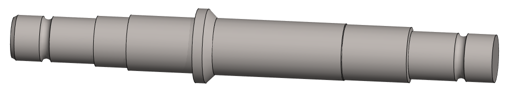
Exercise 7: Axis
This exercise was carried out with version 27.0 (Vertex 2021).
In this exercise you will learn to
-
Using raster as on aid of skeching.
-
Diameter dimensioning of a rotationally symmetrical body in a sketch.
-
Thread markings (visual thread on a cylindrical surface).
Functions to be used:
-
Raster picture.
-
Sketching: Polyline, Two Point Line, Arc with Tree Points.
-
Sketching: Delete Section of Line.
-
Sketching: Change the style of line.
-
Sketching:Line style: Rot.axis
-
Sketching constraints: Distance, Angle and Coincident.
-
Operation: Boss > Revolve.
-
Add Round/Bevel > Single Edge Round.
-
Add Round/Bevel > Single Edge Bevel.
-
Thread symbol.
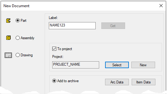
Create a new part
-
File > New > Part.
-
Enter the label (which is also the name of the model and by default will be the name of the drawing).
-
Enter the archive information by clicking Arc.Data.
-
Select the project for the model.
-
OK.
-
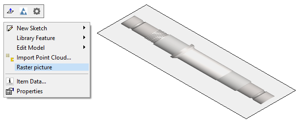
Add a raster to the part model
-
Right-click function: Raster picture.
-
Find and select a raster image.
-
The program places the raster on the XY plane.
Download raster image here (VX_LN7_Akseli.png)
The program validates raster image file formats: Tiff, Jpeg, Bmp, Gif, Png, lwi, pdf and jp2 files.
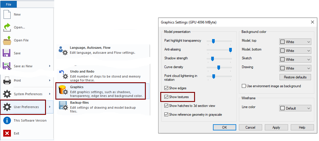
The raster image only appears in the part model and sketch if the auxiliary geometry is visible.
-
Adjust the visibility of the auxiliary geometry with the G key or the toolbar function: Show reference geometry.

If the raster images do not appear on your screen even if you press the G key, check the settings: File > User Preferences> Graphics that Show textures is selected.
Edit the raster image
-
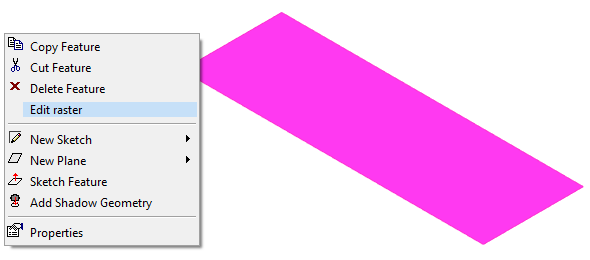
Select a raster from the model's feature tree or click it on the model.
-
Right-click function: Edit raster.
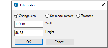
Change size:
-
You can resize the raster by entering the width and height in the appropriate fields.
Set measurement:
-
You can select two points on the raster and give the distance. Program will scale raster to the given dimension.
Relocate:
-
You can flip and move the raster.
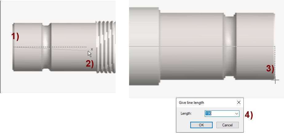
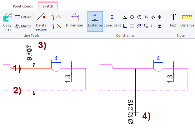
Resize raster by Set measurement function
In the dialog, click the function: Set measurement.
-
The program flips the raster perpendicularly and asks you to select two points.
-
You can zoom the image while pointing the distance.
-
Select starting point, in the figure 1).
-
Aim the cursor at the horizontal line (X-ruler visible) and lock the line by clicking, in the figure 2).
-
Select the end point, in the figure 3).
-
Enter a known length, here 190, in the figure 4).
After this, the raster has the desired size and you can start sketching the shape.
Start sketching
-
New Sketch > To horizontal (XY) plane
Sketch the main shapes using the Polyline
Sketch the axis of symmetry with a two-point line 
-
Style: Rot.axis. (= Axis of rotation).
Sketch a polyline 
-
Use directional locks when sketching lines.
-
Sketch only half the geometry (because the sketch is rotated into an axis with the operation).
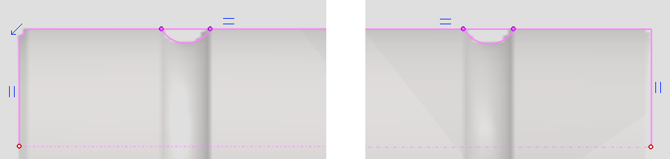
Sketch groove
-
Function: Arc with Tree Points.

-
Select the starting point of the arc from the line.
-
If the program starts drawing a tangential arc, use the Mini Toolbar to remove the feature:

-
-
Select to the point on the circumference of the arc.
-
Click the end point of the arc.
An arc of three points can be drawn on the line tangentially or not tangentially.
-
After you have pointed the first point on the line or from the end point of the line, a Mini Toolbar appears that allows you to define the arc drawing for the indicated line tangentially or freely as a three-point arc.
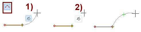
Tangential alternative, in the figure 1).
-
Click the end point of the arc. The arc is drawn tangentially.
Free drawing alternative, in the figure 2).
-
Select to a point on the arc.
-
Select the end point of the arc.
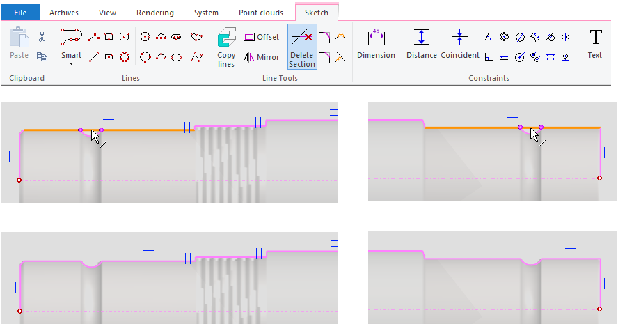
Cut a piece out of the line at the groove
-
Function: Delete Section.
-
Click the line for the section you want to delete.
When you point to a line, it exits to the intersections of the lines.
In the case of a polyline, the assigned segment is deleted.
When you remove a piece from the line segment (as you do in this exercise), the remaining two segments get a constraint of Coincident with each other, i.e. they both lie on the same space line.
-
You can check this by selecting the line and right-click function Properties.
Add a length and groove dimensions to the part
-
Funtion: Distance.
-
Click to the axis end lines and enter 190 as the dimension.
-
Click to the endpoints of the arcs and give the dimension 4.
-
Click the segment and arc at its bottom and enter the dimension 1.3.
-
The G key hides and returns the raster.
If you have the settings Only Wireframe, the G key will not always hide the raster.
-
This depends on how the Shaded/Wireframe button was last pressed.
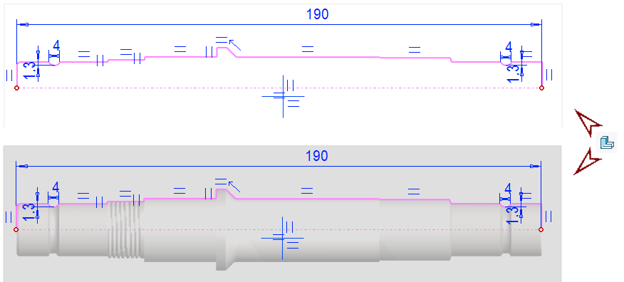
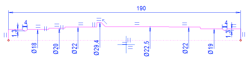
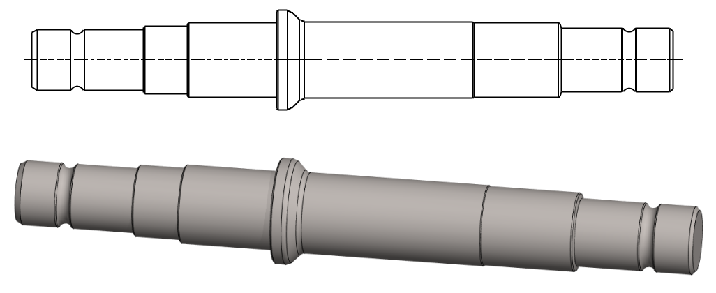
Add diameter dimensions to the shaft
-
Function: Distance. (Dimension constraint is also valid).
-
Click the axis of rotation and the shape line (the order does not matter).
-
Move the cursor to the opposite side of the axis of rotation and a diameter mark will appear in front of the dimension:

-
Select the location of the dimension.
-
Enter the diameter (See dimensions in the picture)
The Distance function can measure either the distance between the lines or the so-called diameters (i.e. 2 * distance).
-
This requires that one of the lines is type Rot.axis. (Axis of rotation).
-
In addition, the lines are required to be parallel.
The dimension type depends on the position of the cursor.
-
If the cursor is on the same side as the Shape line, the program suggests a line spacing (radius), in the figure 3).
-
If the cursor is on the other side of the rotation axis, the program suggests a diameter, in the figure 4).
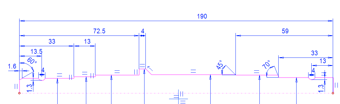
Add distance and angle constraints
-
Function: Distance.
-
Function: Angle.
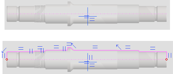
Position the axis of rotation on the center cross.
-
Function: Coincident.
-
Click the axis of rotation and the horizontal line of the center cross.
-
Click the vertical line at the left end of the axis and the vertical line of the origo.
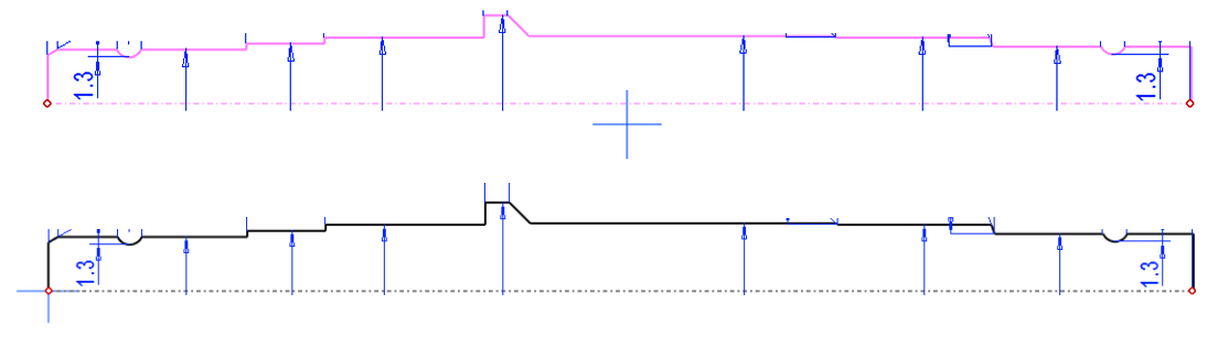
The sketch is now defined. (= all sketch lines are black)
Close the shape of the sketch by drawing a shape line on the axis of rotation.
-
Without this line, the shape line chain will remain open (you will see red dots at the end of the open lines) and you will not be able to rotate it.
Note that if you position the sketch as described above, the raster image will remain in place and can no longer be used to aid in sketching.
-
It's possible that you move the raster as much, but the program doesn't have a good tool for that.
-
Normally, a raster is no longer even needed at this point.
Perform the boss revolve operation
-
Stop sketching (the green OK button).
-
Select: Boss and Revolve.
-
Accept the Lenght or Angle value: 360.
-
Click OK.
Add the necessary bevel and roundings in the part modeling mode.
-
Click a line or lines (Remember Ctrl if you select multiple lines).
-
Right-click function: Add Round/Bevel > Single Edge Round.
-
Right-click function: Add Round/Bevel > Single Edge Bevel.
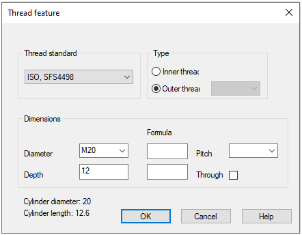
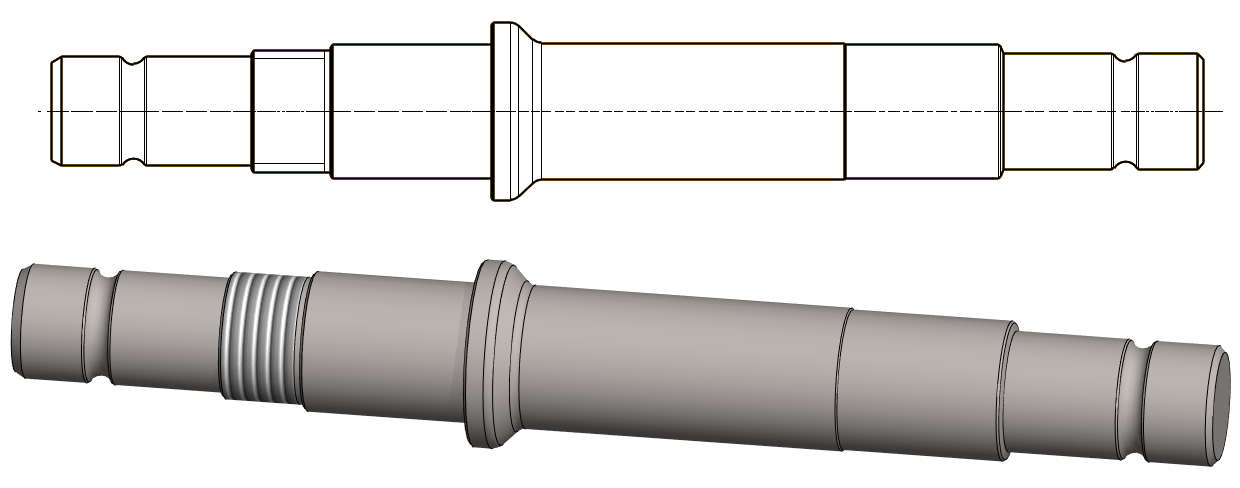
Add a Thrad symbol
-
The thread mark appears in the model as a surface texture, but in the model drawing it appears as a thread.
Add a thread symbol:
-
Click the cylinder surface.
-
Right-click function: Thread symbol.
-
Click the end line of the cylinder surface where the threading begins.
-
Select the data.
Save the model
-
File > Save or click


Further processing of the model (presented in Exercise 5. Swivel lever)
You can add a material item to the model with the right-click function Item Data.
-
These will also appear in the parts list of the model drawing.
You can create a drawing for the model:
-
In the feature tree, select Drawings.
-
Right-click function: New Drawing.