

Exercise 6: Flange
This exercise was carried out with version 27.0 (Vertex 2021).
In this exercise you will learn to
-
Sketching
-
Rotation series in sketch.
-
The Tip box compares the differences between the sketch and feature pattern - the feature pattern is more useful.
-
-
How to make part with Boss Revolve.
-
Line style change.
Functions to be used:
-
New Sketch > To lateral (YZ) plane.
-
Sketching: Polyline, Two Point Line, Circle with Center and Radii Point,
-
Sketching constraints: Dimension, Diameter and Coincident.
-
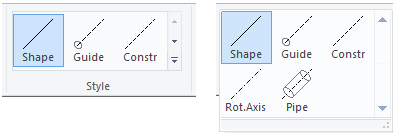
Sketching:Line style: Rot.axis
-
Operation: Boss > Revolve.
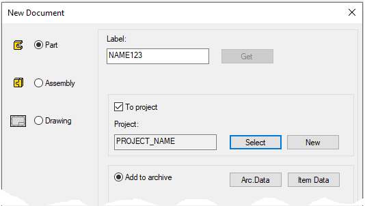
Create a new part
-
File > New > Part.
-
Enter the label (which is also the name of the model and by default will be the name of the drawing).
-
Enter the archive information by clicking Arc.Data.
-
Select the project for the model.
-
OK.
-
Start sketching
-
New Sketch > To lateral (YZ) plane
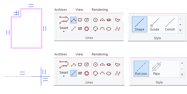
Sketch the geometry
Sketch a cross section
-
A: Binding the back surface of the flange to the origin: Polyline.
-
Line style: Shape.
-
Use the line direction locks (X and Y) to help you draw.
Sketch the axis of rotation
-
Function: Two Point Line.
-
Line style: Rot.Axis (axis of rotation).
-
Click the origo as the first point.
-
Select the end point of the line.
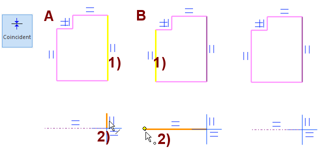
Add the necessary Coincident constraints
A: Tie the back surface of the flange to the origo
-
Function: Conincidet.
-
Click to the line, in the figure 1).
-
Click the vertical line of the center cross, in the figure 2).
B: Tie the length of the axis of rotation to the front of the flange
-
Function: Conincidet.
-
Click to the line, in the figure1).
-
Click to the end point of the axis of rotation, in the figure 2).
The origo of the part model is placed on the cursor when the part is added into the assembly.
-
Therefore, the place of origo in the first sketch is important.
-
In this exercise it is wanted that the default flange attachment point is exactly on the back face of the flange.
The axis of rotation is always shown in the part as an auxiliary geometry.
The end points of the axis of rotation can be used in the positioning of the part of the assembly
-
For this reason, it is advisable to give the axis of rotation a precisely defined length.
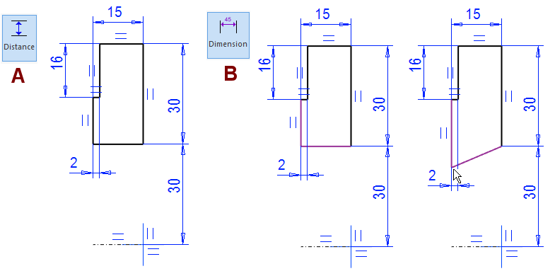
Add dimensions
Add distance constraints mainly by pointing lines, not points, because the lines will get parallelism at the same time.
In figure A, the constraints are given by the Distance function, so the lowest shape line is not dragged to anything.
In figure B, the constraints are given by the Dimension function, so you can drag the lowest shape line.
-
In the case of B, this line could be oriented horizontally under either the parallel or perpendicular constraint, depending on the second assigned line.
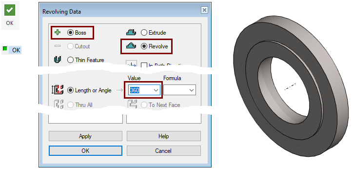
Perform the boss revolve operation
-
Stop sketching (the green OK button).
-
Select: Boss and Revolve.
-
Accept the Lenght or Angle value: 360.
-
Click OK.
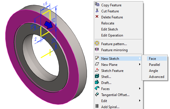
Start creating a new sketch
-
Click the face of the part.
-
Right-click function: New Sketch > Face.
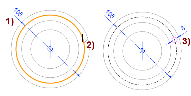
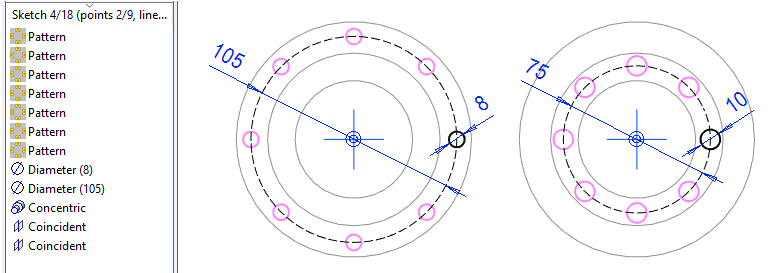
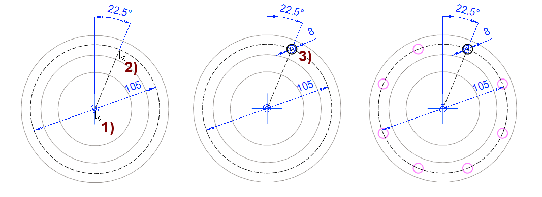
Draw a help circle and dimension it
-
Function: Circle with Center and Radii Point

-
Note style: Guideline.
-
Click the origo as the first point (center of the blue cross).
-
-
Function: Add diameter constraint.

-
Value: 105, in the figure 1).
-
Sketch a hole
-
Function: Circle with Center and Radii Point
-
Note style: Shapeline.
-
Select the location of the center above the guideline, in the figure 2).
-
Select the location of a point on the circumference of the circle.
-
-
Function: Add diameter constraint.
-
Value: 8, in the figure 3).
-
-
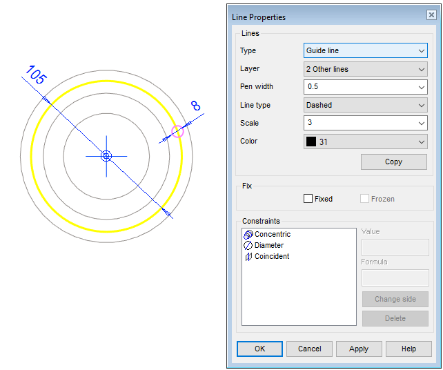
Select the line or lines and then select the line style.
-
Double-click the line or
-
Select the line and right-click function: Properties.
-
You can edit the individual properties of the line, of which only the Type selection is relevant for the operation (extrusion, rotation, etc ...).
-
The box shows which constraints affect the line
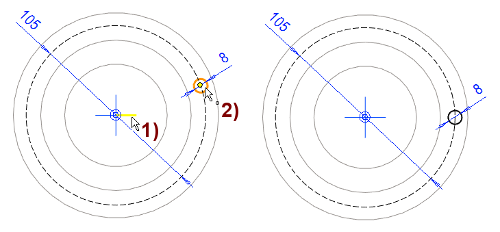
Position the hole on the same level as the horisontal line of center cross
-
Function: Coincident.
-
Click the horisontal line of the center cross, in the figure 1).
-
Click the center of the circle, in the figure 2).
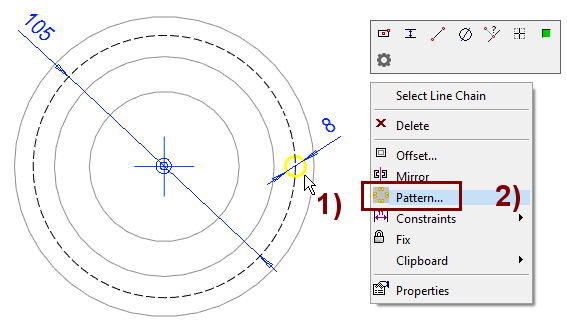
Createa sketch hole and a polar pattern
-
Select the line of hole, in the figure 1).
-
Right-click function: Pattern, in the figure 2).
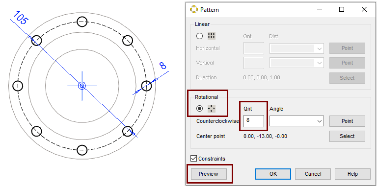
Specify the properties of the pattern
-
Select a pattern type: Rotational.
-
Enter the quantity of members in the pattern: 8.
-
OK adds pattern.
By default, the rotation pattern of the sketch is always drawn around the origo.
-
Use the Angle value if the members of the pattern are not evenly spaced over the entire circle, but at regular intervals.
-
Use the Select button to select the location of the center of the pattern.
Editing a pattern in a sketch does not fully meet the same requirements as editing a feature pattern.
However, you can edit:
-
The position of the pattern relative to the origo.
-
You can change the dimensions of the pattern.
You cannot edit the quantity of members in a sketch pattern.
-
For this reason, this kind of holes should be done as a feature pattern.
However, if you make a sketch pattern and later want to change the quantity of members in the pattern, delete all the elements in the pattern and re-create the pattern.
If the holes in the flange were threaded holes, they would definitely be made with a threaded feature and a pattern of features made from it.
-
In the case of a sketch pattern, each hole should be individually defined as a threaded hole.
You can also easily edit in the feature pattern:
-
The members in the series.
-
The place of the members in the pattern. (e.g. the angle between the members in the pattern).
The feature pattern can be utilized later in the assembly.
-
When a part is brought to the assembly, e.g. a screw into the holes in the flange, then the program can only suggest making a pattern of screws if the pattern has been made by using a pattern of features.
Perform the cutout extrusion operation
-
Stop sketching (the green OK button).
-
Select: Cutout and Extrude.
-
Select: Thru All.
-
Click OK.
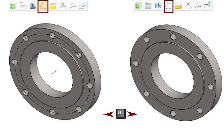
Correct positioning of the hole pattern from the point of view of machine design
When the parts are placed in the assembly, the part is in the cursor in the position in which it was modeled.
-
The part can be rotated about the X, Y and Z axes during placement.
-
Finally, the part can always be positioned in the desired position on the constraints.
Of course, if possible, the part should be modeled so that the part is in the correct position immediately at the time of placement, so that work is as fast as possible.
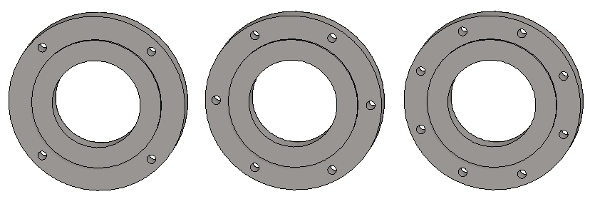
In the figure above, the holes are not located in the most optimal place in terms of strength, e.g. when gravity acts on a pipeline at the ends of which the flanges in that position would be.
The holes should be located so that the two screws carried a similar load, i.e., the holes should not be located with respect to the center of the flange in its vertical or horizontal line.
The figure below shows the correct positioning of the holes when the force acts in the from top to bottom.
Create a correct sketch of the location of the holes
-
The previous hole has been removed.
-
Add a guideline from the origo to the help circle, in the Figures 1) and 2).
-
Drag the line to make sure its endpoint coincides with the help circle.
-
If not, add a coincides constraint between the endpoint of the guideline and the help circle.
-
-
Add a circle to the endpoint of the guideline, in the Figure 3).
-
Enter the diameter: 8.
-
-
Then make a series as described above.
-
Rotational.
-
Qnt: 8.
-
The preview shows the place of the pattern.
-
OK to place the series.
-
Save the model
-
File > Save or click


Further processing of the model (presented in Exercise 5. Swivel lever)
You can add a material item to the model with the right-click function Item Data.
-
These will also appear in the parts list of the model drawing.
You can create a drawing for the model:
-
In the feature tree, select Drawings.
-
Right-click function: New Drawing.
Download the first version of flange (VX_LN6.vxm) here
Download a flange model with the correct hole placement (VX_LN6A.vxm) here.