Exercise 5: Swivel lever
This exercise was carried out with version 27.0 (Vertex 2021).
In this exercise you will learn to
-
Draw lines with the function Smart (Smart line chain.)
-
Use sketching tools symmetry, equal distance, equal radius, angle and distance.
-
Add parts list information (Bill of materials.)
-
Create drawing for the model
Functions to be used:
-
Sketching: Smart line chain.
-
Sketching: Circle with center and radii point.
-
Sketching constraints: Symmetry, Distance, Angle, Equal distance and Equal radius constraint.
-
Operation: Boss > Extrude and Cutout > Extrude
-
Item Data
-
New Drawing
Model the swivel lever
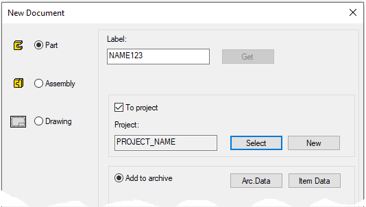
Create a new part
-
File > New > Part.
-
Enter the label (which is also the name of the model and by default will be the name of the drawing).
-
Enter the archive information by clicking Arc.Data.
-
Select project for the model.
-
Click OK.
-
Start sketching
-
New Sketch > To vertical (XZ) plane
Draw a line chain
-
Line drawing is taught in Exercise 3. Collar - Smart line chain.
-
So only the main features of the sketch are described here.
-
Then draw lines so that the blue cross remains inside the area.
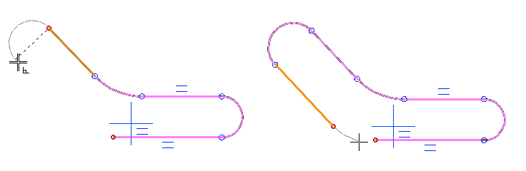
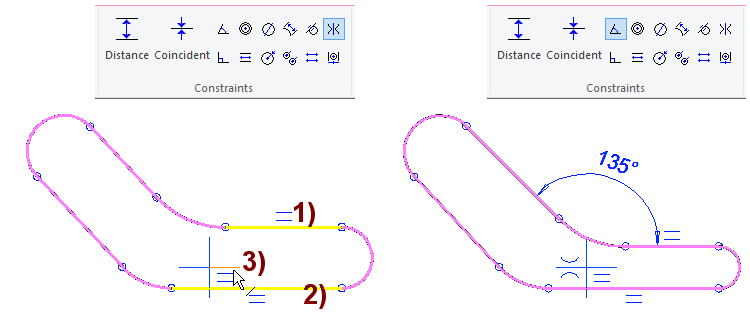
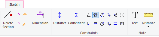
Add a symmetry constraint
-
Function: Symmetry.
-
Click to the first line, in figure 1).
-
Click to the second line, in figure 2).
-
Selec to the symmetry axis, in figure 3).
Add a angle constraint
-
Function: Angle.
-
Click to the first line.
-
Click to the second line.
-
Select the location of the dimension.
-
Enter the correct value: 135.
As explained in previous exercises, the symmetry and angle constraint can also be started by first selecting two lines (the latter with the Ctrl key pressed).
-
Then select mouse right click function: Constraints > Symmetry or Angle.
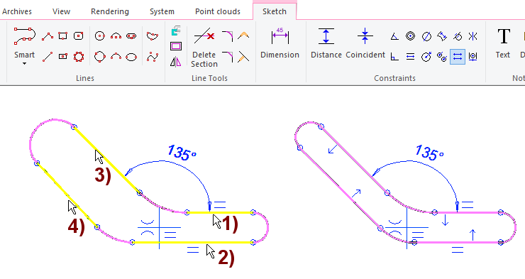
Make branches of the swivel lever same width using the equal distance constraint
-
Function: Equal distance.
-
Click to the first line, in figure 1).
-
Click to the second line, in figure 2).
-
Click to the third line, in figure 3).
-
Click to the fourth line, in figure 4).
The constraint is given by indicating the elements (line or point) in pairs:
-
The distance between the first and second elements is set as the distance between the third and fourth lines, unless other conditions don't prevent this.
-
Select four elements (here lines) in pairs (2 ... 4th line Ctrl key pressed)
-
Right-click function: Constraints > Equal Distance
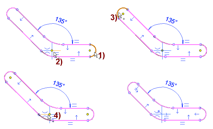
Make branches of the swivel lever the same length using the equal distance constraint
-
Function: Equal distance.
-
Click to the first dot, in figure 1).
-
Click to the second dot (center point of blue cross), in figure 2).
-
Click to the third dot, in figure 3).
-
Click to the fourth dot (center point of blue cross), in figure 4).
Give width and length of the swivel lever
-
Width: 40.
-
Length (vertical line of origo and center of the arc): 100.
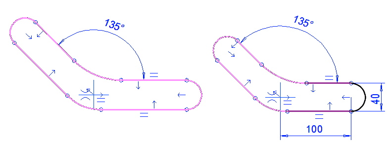
Stabilize the angle position by drawing a construction line.
Try to drag the geometry. Figure A).
-
Drag the geometry (eg. the center of the upper arc) and carefully move the cursor.
-
You can cancel dragging by pressing Undo

Draw a construction line. Figure B.
-
Fuction: Two-Point Line
-
Click origo, figure 1).
-
Click inner arc (he center of the arc), figure 2).
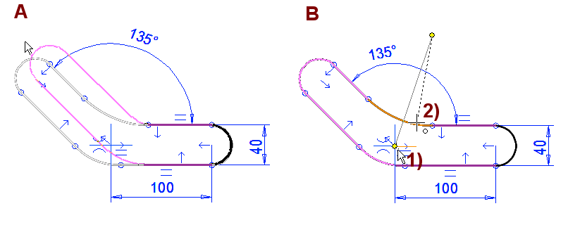
Give the angle of the construction line
-
Function: Angle.
-
Click the first line.
-
Click the second line.
-
Select the location of the dimension.
-
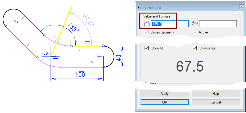
Enter the correct value: 135/2.
You can also use mathematical expressions (+ - * / etc)
-
Get more information about this in the Online Help (F1), Select Search > formulas
You can see the value of the calculation formula in the dialog (figure 67.5).
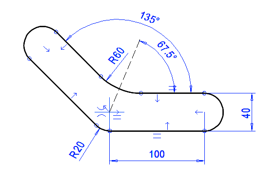
Give the radius of the corners
-
Function: Angle.
-
Click the arc.
-
Select the location of the dimension.
-
Enter the correct value: 20 and 60.
The draft is now defined. Only the length of the construction line is undefined, but it is irrelevant to the outcome.
-
All lines should be black (except for that construction line).
-
You can't anymore change the geometry by dragging.
Perform the boss extrusion operation
-
Stop sketching (the green OK button).
-
Select: Boss and Extrude.
-
Select: Length or Angle and enter the value: 6.
-
Click OK.
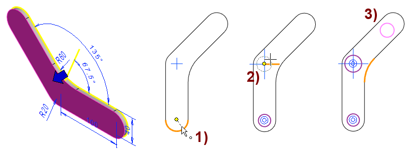
Sketch the holes
-
Select face.
-
Right-click function: New Sketch > Face.
Draw circles
-
Function: Circle with Center and Radii Point.
-
Select the center of the circle.
-
Select the circumference.
-
Center of the first circle is the center of the arc. There is a concentricity between these, figure 1).
-
The center of the second circle is the origo. There is a concentricity between these, figure 2).
-
Draw the center of the third circle freely, figure 3).
Give the concentric constraint
-
Function: Add concentricity constraint.
-
Click the center of the circle.
-
Click the center of the arc.
-
Click the first dot.
-
Press Ctrl key and click the second dot.
-
Right-click function: Constraints > Concentric.
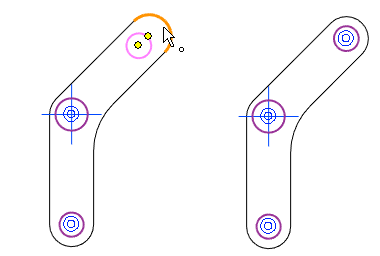
Set equal radius
-
Function: Add equal radius constraint.
-
Click the first circle, in figure 1).
-
Click the second circle, in figure 2).
When you select the equal radius constraint and click any circle the equal radius symbol appears next to the cursor.

-
1: Select the other two circles (by default the first-clicked circle retains the diameter unless the second-clicked circle has constraint that limit its size).
-
2: You can select several circles and they all get the same radius as the first circle.
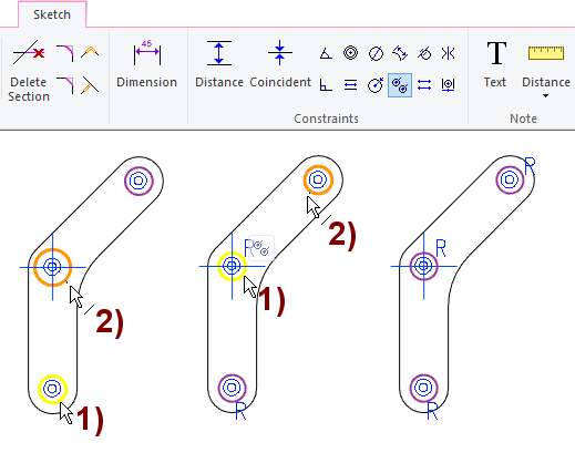
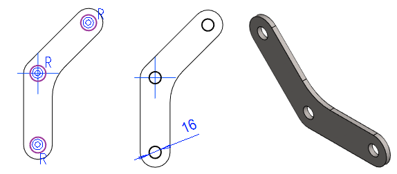
Give diameter of circles and perform the Cutout Extrusion
-
Diameter: 16.
-
Boss extrusion operation
-
Click OK

-
Select: Cutout and Extrude.
-
Select: Thru All.
-
Click OK.
-
Item data and drawing
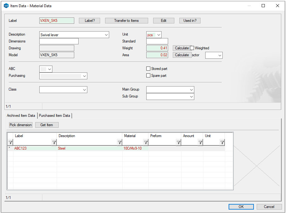
Add material information
-
Mouse Right-click function when the element is not selected (empty space): Item Data.
The upper part of the dialog
Contains part item information
-
You can calculate the weight by pressing Calculate button next to the Weight field (you must first select raw material or density)
-
You can calculate the area of the paragraph pressing Calculate button (next to the Area field).
Lower part of the dialog:
Contains raw material information.
-
Fill in the information
-
The material column has a preselection button that allows you to retrieve material information.
-
In the Label field, enter the stock identification (item) used in your company for the raw materials.
The Item Data of the raw materials, components and profiles is stored in the d_COMPONENTS database.
-
You can edit this: System tab > Application > Item Database: Browse and Edit.
-
For more information, see Online Help (F1): Part Item Data and Edit a Vertex Database.
The data can be imported from ERP into the Vertex Item Database using Excel.
G4 can also be connected to the Vertex Flow PLM program.
Save the model
-
File > Save or click


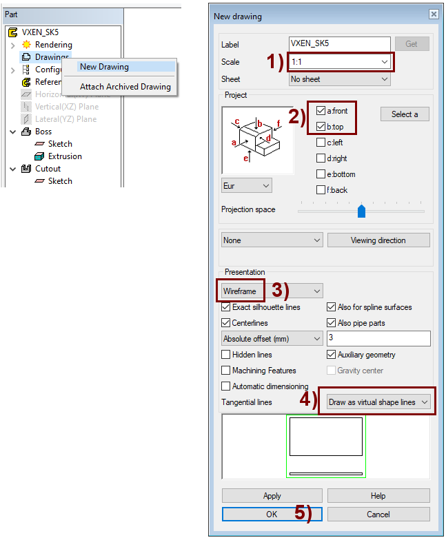
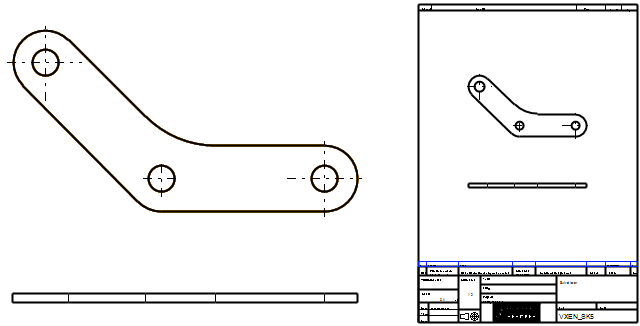
Create the drawing
-
In the feature tree, select Drawings.
-
Right-click function: New Drawing.
Adjust
1) Scale
-
A scale that depends on both the size of the model and the drawing sheet and the projections desired for it.
-
Use the preselection button to find the standard scales in the drawing and select the appropriate one.
-
In this exercise 1:2.
-
If you have selected drawing sheet, you can see (at the bottom of the dialog) how well those projections fit on the sheet.
2) Projections
-
Choose necessary projections: front, top, etc.
-
You can see what the front projection will look like if you turn the model in the front direction
-
You can also click the Select a to select a face on your model that defines the so-called Front direction.
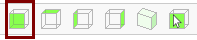
3) Settings of Presentation
-
Select Wireframe.
-
You can also choose e.g. that the center lines or hidden lines of the cylinder surfaces and holes be drawn on the model.
-
For tangential lines, 4) in the figure, select As a thin line, so that the boundary line between the face and the cylinder surface is not drawn as a contour line.
5) Click OK
-
Generate selected projections from the model into the drawing.
Read more in the Online Help (F1): Geometry 2D> Model drawing.
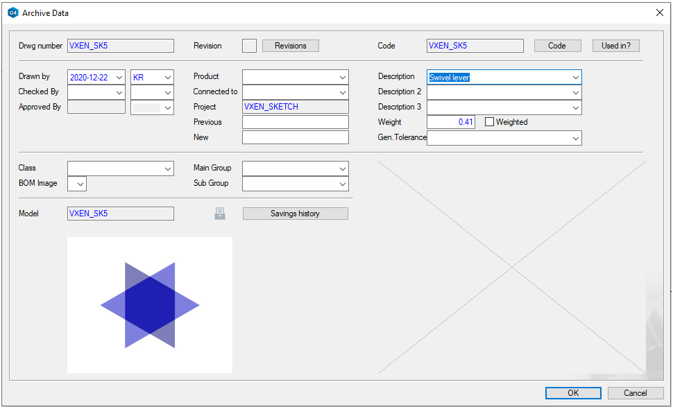
Fill in the archive data for the drawing
-
Vertex generates the requested projections and copies the model archive data to the drawing archive card.
-
Edit and complete archive information if needed.
-
OK completes the drawing creation.
Add a sheet to the drawing
-
If you selected a sheet in the previous dialog, the program will add it automatically.
-
After this, you should often drag the sheet to a better location before dimensioning the drawing.
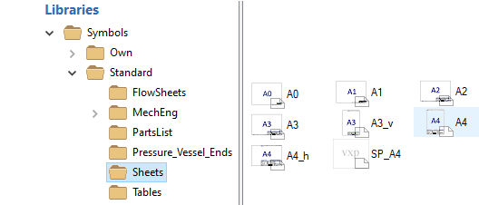
Add a sheet
-
Right-click function: Read Symbol.
-
Double-click the sheet you want.
-
Place the sheet on the drawing.
Save the drawing and close it
-
File > Save or click
Save the model
-
Saving the model after creating the drawing is absolutely important, otherwise it will not be marked in the model feature tree.
-
The drawing can be found in the feature tree under the Drawing.
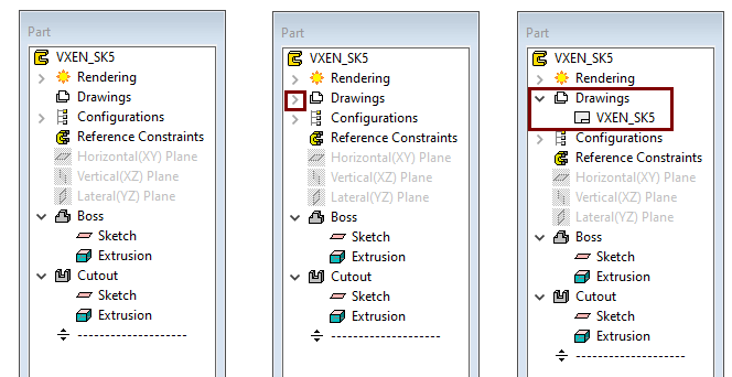
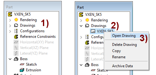
Opening the model drawing
-
Open the List of Drawing from the feature tree, in figure 1).
-
Select the drawing, in figure 2).
-
Right-click function: Open Drawing.