Exercise 12: Texts in the part
This exercise was carried out with version 27.0 (Vertex 2021).
In this exercise you will learn to
-
To add texts to the part.
-
To mirror the texts to be added into the sketch.
-
To mirror the features.
Functions to be used:
-
Sketching: Two Point Rectangle, Acr with Tree Points and Text.
-
Sketching constraints: Distance, Symmetry and Radius.
-
Operations: Boss Extrusion and Cutout Boss Extrusion.
-
Part: Feature Mirroring.
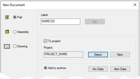
Create a new part
-
File > New > Part.
-
Enter the label (which is also the name of the model and by default will be the name of the drawing).
-
Enter the archive information by clicking Arc.Data.
-
Select the project for the model.
-
OK.
-
Start sketching
-
New Sketch > To lateral (YZ) plane
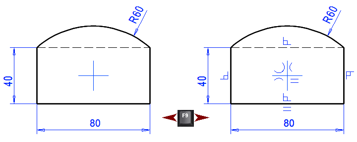
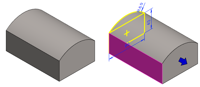
Sketch the body
-
Function: Two point rectangle (Start at the origo)..
-
Function: Acr with Tree Points. (Without tangentiality).
Edit:
-
Top horizontal line properties: Construction line.
Constraints:
-
Dimension or Distance.
-
Radius.
-
Dimension constraints are always displayed.
-
The symbols for other constraints are shown or hidden with the F9 key.
Perform the boss extrusion operation
-
Stop sketching (the green OK button).
-
Select: Boss and Extrude.
-
Select: Length or Angle.
-
Enter the value: 120.
-
Click OK.
Create a sketch on the front face
-
Click the face of the part.
-
Right-click function: New Sketch > Face,
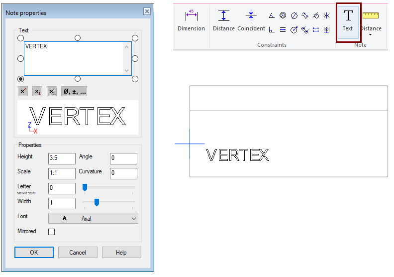
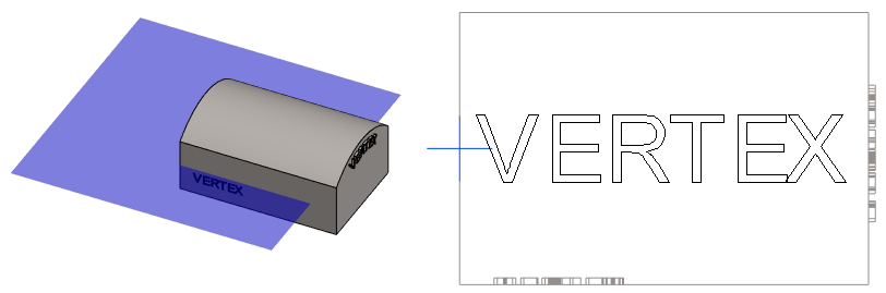
Add text
-
Right-click function: Text (Add Text)
-
Enter text, e.g. VERTEX.
You can affect the height of the text with the Height field and the Scale field.
-
Enter 3.5 for height and 1:2 for scale or
-
Enter 7 for height and 1:1 for scale.
-
Place the text manually. (Text cannot be placed with constraints.)
-
Press Esc to stop entering text.
If the drawing is made on a scale of 1:1, then the height given here, e.g. 3.5mm, is shown as it is in the drawing.
If the drawing is made on a scale of 1:5 and you want the text to appear in the drawing at a height of 5 mm, it is advisable to give a height of 5 and a scale of 1:5 or a height of 25, with the scale remaining 1:1.
Also note the radio buttons around the Text box, which allows you to adjust the text hang points relative to the cursor.
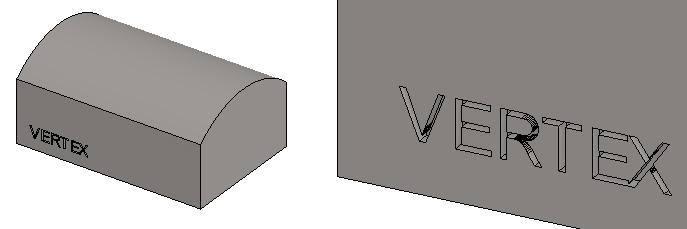
Perform the cutout extrusion operation
-
Stop sketching (the green OK button).
-
Select: Cutout and Extrude.
-
Select: Length or Angle.
-
Enter the value: 2.
-
Click OK.
Add curved text to the end face of part
-
Click the end face and the Right-click function: New Sketch > To Face.
Add text, eg VERTEX
-
Height: 3.5
-
Scale: 1:2
-
Curvature: -50
-
Letter spacing: 0.5
-
Place the text.
-
Press Esc to stop entering text.
Perform the boss extrusion operation
-
Stop sketching (the green OK button).
-
Select: Boss and Extrude.
-
Select: Length or Angle.
-
Enter the value: 2.
-
Click OK.
Curvature = Indicates the curvature of the center of the text.
-
A positive curvature produces a "Smile Face" curvature.
-
A negative curvature produces a "Sad face" curvature.
Letter spacing = The default value comes with an empty value.
-
A positive value increases the space between letters.
-
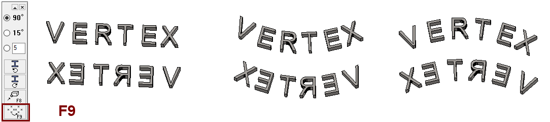
A negative letter spacing narrows the letter spacing or even reverses the order of the letters "from right to left to read."
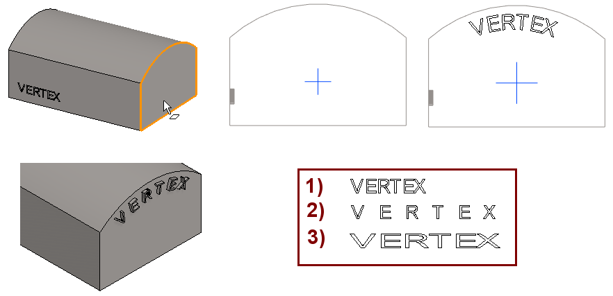
1) Normal text (Width: 1 and Spacing: blank).
2) Letter Spacing 1 (and Width 1).
3) Width 2 (and Spacing: blank).
Extrude the text from the surface past
-
Right-click function: New Sketch > To horizontal (XY) plane
-
Or if the auxiliary levels are visible, then to the face of the horizontal plane.
-
Add text, e.g. VERTEX
-
Height: 20
-
Scale: 1:1
-
Curvature: blank
-
Letter spacing: blank
-
Place the text.
-
Press Esc to stop entering text.
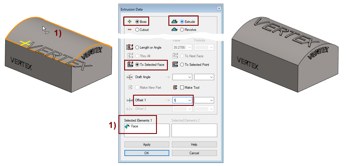
Perform the boss extrusion operation
-
Stop sketching (the green OK button).
-
Select: Boss and Extrude.
-
Select: To Selected Face
-
Click the Face
-
-
Enter the value: 1.
-
Click OK.
The positive offset value of the extrusion extends the extrusion to a face parallel to the clicked face, which is by an Offset value above the clicked face.
-
In this exercise, the extrusion starts moving in the middle of the part and extends by the surface + Offset past the surface.
If the sketching plane had been outside the part and the extrusion had been done on the selected surface with a positive offset value, then the extrusion would not have extended to the surface but remained "in the air" by the value of the offset.
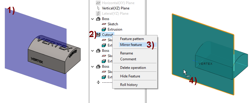
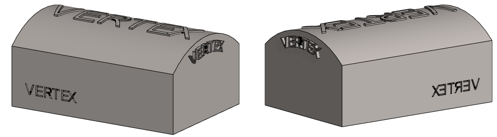
Mirror the first text feature to the other side of the part.
For mirroring, display the basic auxiliary level of the part: Vertical (XZ) plane, in the figure 1).
-
In the feature tree, select Vertical (XZ) plane (if the plane is hidden).
-
Right-click function: Restore.
Mirror the feature
-
Select the (second) feature from the feature tree, in the figure 2).
-
Right-click function: Feature Mirroring, in the figure 3).
-
Click the mirror plane, in the figure 4).
Save the model
-
File > Save or click


Mirroring of texts
You can also mirror the text in the sketch during the placement phase.
-
Use the button in the figure below or the F9 key.