

Exercise 9: Seal
This exercise was carried out with version 27.0 (Vertex 2021).
In this exercise you will learn to
-
Mirror the sketch geometry.
-
Sketch placement on the guide curve.
-
Operations: Guide curve and Cross Section.
-
Sweep.
Functions used
-
Sketching: Smart line chain, Two Point Line, Acr with Tree Points.
-
Sketching constraints: Distance, Radius, Angle.
-
Sketching: Delete Section of Line.
-
Sketching: Mirror.
-
Sketching: Round.
-
New Sketch (When the line segment is selected).
-
Operation: Guide curve.
-
Operation: Cross Section.
-
Part: Sweep.
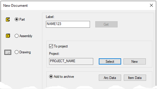
Create a new part
-
File > New > Part.
-
Enter the label (which is also the name of the model and by default will be the name of the drawing).
-
Enter the archive information by clicking Arc.Data.
-
Select the project for the model.
-
OK.
-
Start sketching
-
New Sketch > To horizontal (XY) plane To vertical (XZ) plane To lateral (YZ) plane
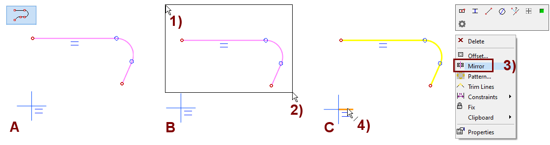
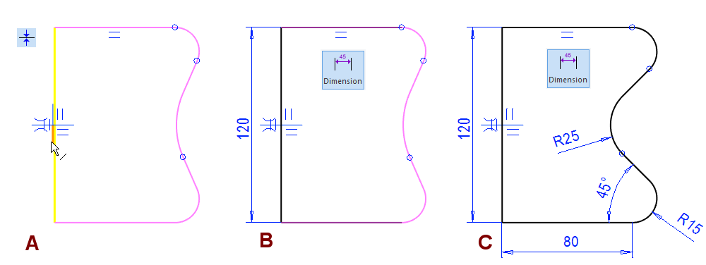
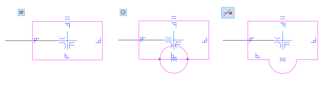
Sketch the part of the control curve to be mirrored and mirror it
-
Function: Smart Line Chain.
-
Sketch a line chain, in the figure A.
-
Stop the function (Press Esc or Middle button of Mouse).
-
-
Fence the geometry, in the figure B.
-
Select a point in space (when no function is in progress), in the figure 1) and hold down the mouse button.
-
Move the cursor so that the selected geometries remain inside, in the figure 2).
-
Release the mouse button. Now the elements are selected.
-
-
Mirror the geometry, in the figure C.
-
Right-click function: Mirror, in the figure 3).
-
Click the horizontal line of the origo as the mirror line, in Figure 4).
-
Gets symmetry conditions automatically.
Complete the sketch with a line and an arc.
-
Function: Two Point Line.
-
Function: Acr with Tree Points.
-
Note that the tangentiality option is selected for the arc
-
If not, select it from the Mini Toolbar.
-
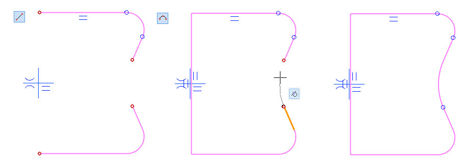
Give Coincidence and dimensions
-
Function: Coincident.
-
Click to the line, in the figure A).
-
Click the vertical line of the center cross.
-
-
Function: Dimension.
-
You can add all the dimensions shown in the figure with the function Dimension.
-
Instead, you can also use constraints: Distance, Angle and Radius.
-
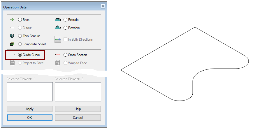
Perform the guide curve operation
-
Stop sketching (the green OK button).
-
Select: Guide Curve.
-
Click OK.
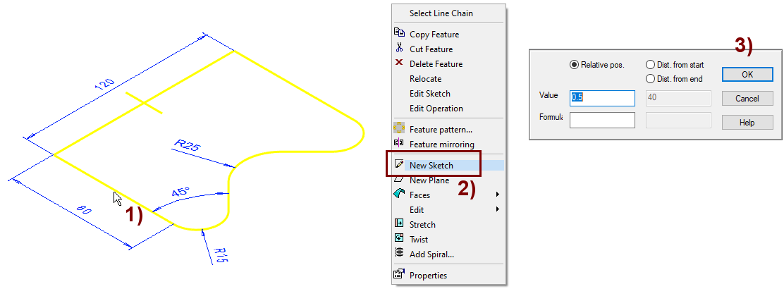
Create a sketch for the Guide curve
-
Select one line from the control curve, in Figure 1).
-
Right-click function: New Sketch, in Figure 2).
-
Accept the relative position of the sketch (0.5) with a line, in Figure 3).
The selected line can be a segment, a circle, an arc, an ellipse, a spiral, a sline or the line edge of a part.
If the intention is to create a Sweep, then the sketch may be located anywhere on the line. The default point, in the middle, then works well.
If the intention is to create a Loft, in which the line has several different cross sections, the following dialog can be used to determine the location of the sketch (and cross section).
-
Relative pos.: value 0 ... 1 (0 represents one end of the line and 1 represents the other end).
-
Dist. from the start: Enter the distance (in millimeters) from the first end of the line.
-
Dist. from the end: Enter the distance (in millimeters) from the second end of the line.
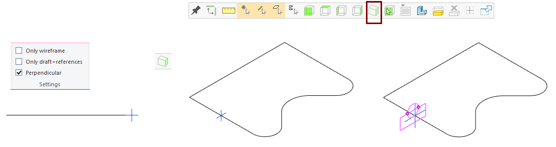
Check the view of the model before starting to sketch
-
If Perpendicular is selected in the sketch settings, the sketch may be in the position, the direction you think is up is down.
-
It is advised to start sketching first in an isometric projection and then turn the sketch in a perpendicular direction with the Right-click function: Perpendicular.
Sketch the cross-sectional shape of the seal
Sketch a rectangle:
-
Function: Two point rectangle.
-
Click the origo as the first point (center of the blue cross).
-
Click the second point.
Sketch a circle:
-
Function: Circle with Center and Radii Point.
-
Click the center of the lower segment. (So that the center of the circle gets the conincident constraint on the line).
-
Select the location of a point on the circumference of the circle.
Remove unnecessary line segments:
-
Function: Delete Section of Line.
-
Click the portion of the lines you want to delete.
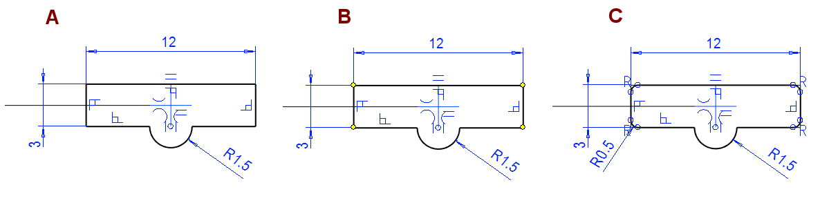
Add dimensions and round corners
Add dimensions:
-
Function: Dimension. (or functions: Distance and Radius), in Figure 1).
Round the corners:
-
Function: Round.
-
Select four corner points, in Figure B).
-
The second, third, and fourth points are selected by pressing the Ctrl key.
-
-
Right-click function: Round.
-
Enter the radius: 1.5.
Perform the cross section operation
-
Stop sketching (the green OK button).
-
Select: Cross Section.
-
Click OK.
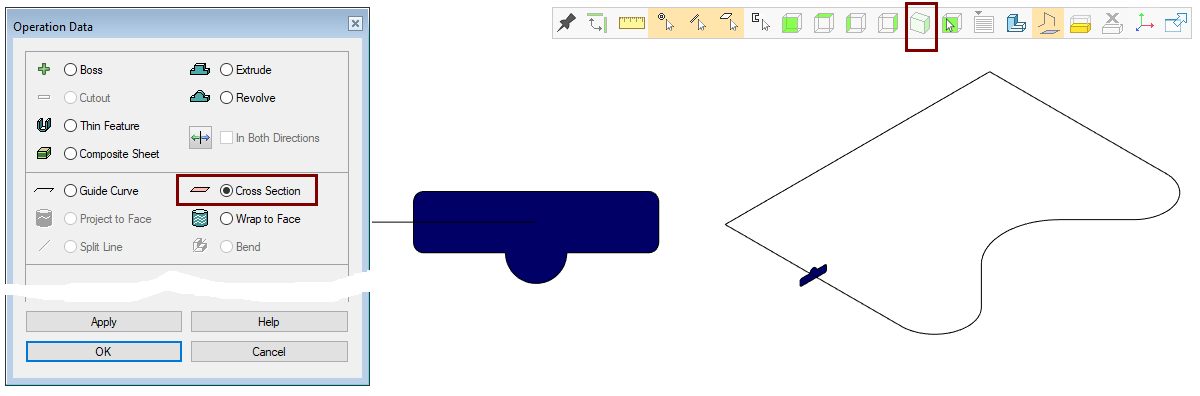
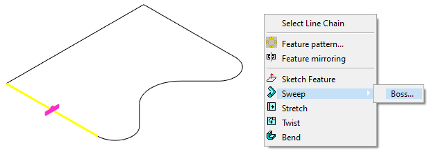
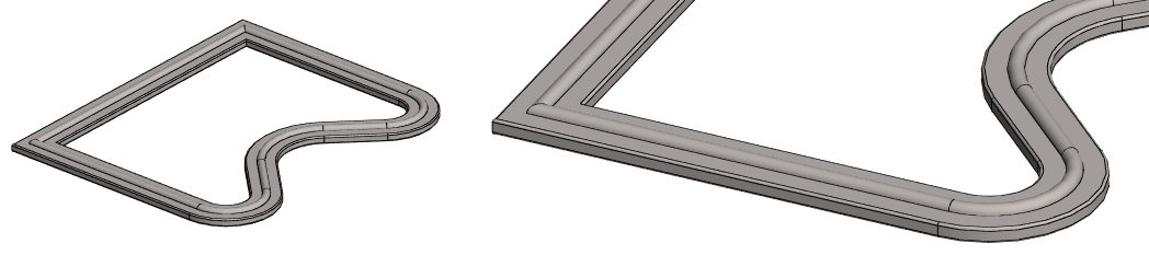
Create a part by swiping the cross section along the line chain
-
Click a line and cross section. (Second element with Ctrl key)
-
Right-click function: Sweep > Boss.
-
The program opens the Sweep dialog.
-
You can study more about this in the OnLine Help (F1).
-
-
Function: Add boss using cross-section from library.

-
Select a cross section from the Profile library.
-
Click the guide curve line or edge of part.
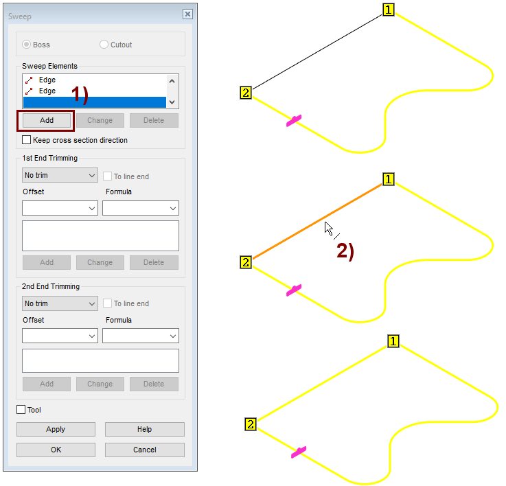
Select the last line to be swept
-
Click: Add, in Figure 1).
-
Click the line to add, in Figure 2).
-
Right-click function: OK (Add the selected line to the list of Sweep Elements).
-
OK
The program finds all lines tangential to the selected line and adds them as Sweeping Elements.
-
If necessary, you can add lines that belong to the same line chain (but not tangential) using the Add.
-
If necessary, you can delete tangential lines. Use the Delete.
-
The dialog also includes the possibility that the sweep can be trimmed from either end to either a surface, a section, or a point.
-
If necessary, an offset can be entered for this trimming.
-
Note that the cross-section must be able to pass through the arcs of the steering geometry so that it does not have to rotate around itself.
Save the model
-
File > Save or click


Further processing of the model (presented in Exercise 5. Swivel lever)
You can add a material item to the model with the right-click function Item Data.
-
These will also appear in the parts list of the model drawing.
You can create a drawing for the model:
-
In the feature tree, select Drawings.
-
Right-click function: New Drawing.