

Exercise 2: Triangle and polygon
This exercise was carried out with version 27.0 (Vertex 2021).
In this exercise you will learn to
-
How you can sketch to the auxiliary plane and plane face.
-
Adding a polygon and a parallelism constraint.
-
Perform Boss Extrusion and Cutout Extrusion.
Functions to be used:
-
New Sketch > To horizontal (XY) plane.
-
New Sketch > Face.
-
Sketching: N-gon (Polygon)
-
Operation: Boss Extrusion.
-
Operation: Cutout Extrusion.
Polygon modelling
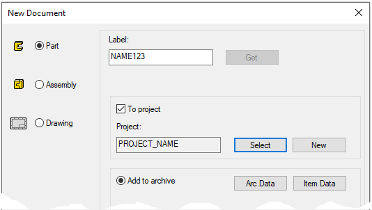
Create a new part
-
File > New > Part.
-
Enter the label (which is also the name of the model and by default will be the name of the drawing).
-
Enter the archive information by clicking Arc.Data.
-
Select the project where the model will be saved.
-
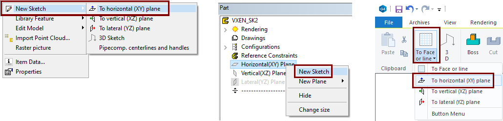
Start sketching
There are several possibilities in the interface where you can choose to create a new sketch for the auxiliary plane.
-
New Sketch > To horizontal (XY) plane.
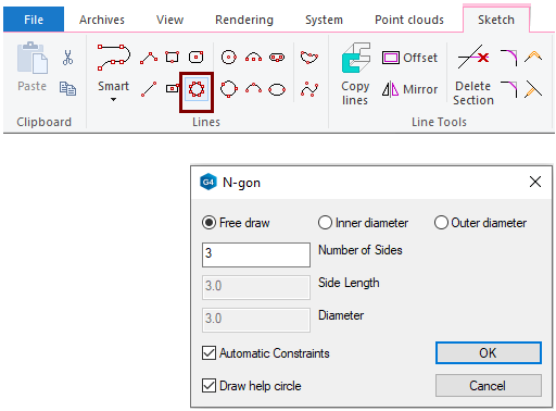
Draw a triangle
-
Funcktion: N-gon.
-
Dialog N-gon is opened
-
-
Select: Free draw.
-
Enter the number of Sides: 3.
Drawing methods:
-
Free draw: Draw the polygon freely.
-
Inner diameter: You can enter either the diameter of the circle drawn inside the polygon or, alternatively, the length of a single sides.
-
Outer diameter: You can enter either the diameter of the circle drawn around the polygon or, alternatively, the length of a single sides.
Number and dimensions:
-
Number of Sides.
-
Side Lenght: If you enter a side length, the program calculates the diameter.
-
Diameter: If you enter a diameter, the program calculates the Side length.
Constraints and help circle:
-
Automatic Constraints: As a general rule, you should always keep this choice.
-
Draw help circle: When you want to use the auxiliary circle, for example, to position other sketch geometry.
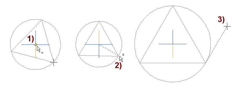
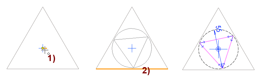
If the polygon is the first feature of the part, we recommend that the center point is selected as the origin sketch (center of the blue cross), in figure 1).
If you want one of the sides to be horizontal or vertical, move the cursor so that the X or Y symbol appears next to it.
-
In this case, click the mouse left button to lock the direction, in figure 2).
Move the cursor to get the triangle of the desired size, In figure 3).
-
If you had selected Inner Diameter or Outer Diameter as the drawing method, a third pointer would be needed to "nail" the triangle into place.
Stop drawing triangles:
-
By starting another function, eg Diameter or
-
Press Esc key or
-
Click the middle mouse button.
Enter a dimension to the Side of the triangle
-
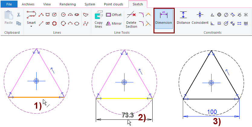
Function: Dimension.
-
Click the line, figure 1).
-
Select the location of the dimension, figure: 2).
-
Enter the correct value: 100.
-
The program scales the triangle to the correct size and adds a Distance constraint, figure: 3).
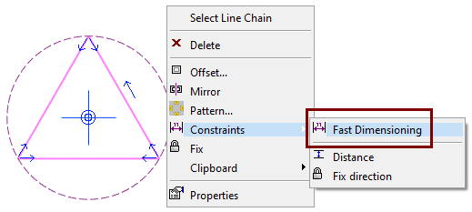
-
-
First select the line to be dimensioned.
-
Right-click function:
-
Select the location of the dimension.
-
Enter the correct value.
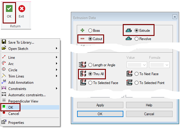
Stop sketching and go to the operation
-
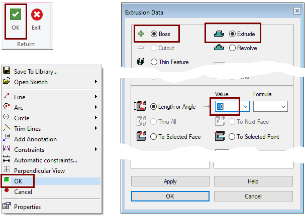
Click OK on either the ribbon or the Right-click menu.
-
The program jumps to the Extrusion Details menu.
-
Select: Boss and Extrude.
-
Enter 10 as the length measure.
-
Accept operation: OK.
-
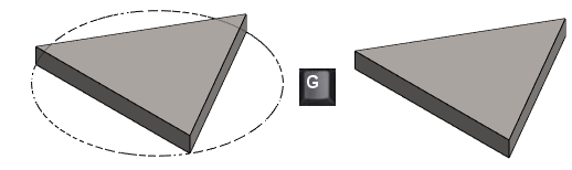
Display auxiliary geometry (guide line)
-
If you selected to a draw help circle for the polygon, the circle is drawn as a guide line.
-
You can hide and show the auxiliary geometry with the key G.
-
If necessary, the auxiliary geometry is also shown in the drawing.
If you want the help circle to appear only in the sketch, but never in the model, then.
-
Edit the sketch.
-
Select circle.
-
Under Style, select Guideline.
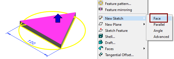
Create a new sketch on the face
-
Select Fase.
-
Right-click function: New Sketch > Face
Sketch a triangle
-
Funcktion: N-gon.
-
Dialog N-gon is opened
-
-
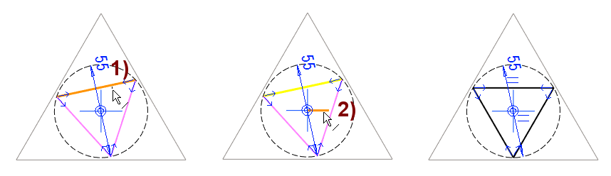
Select: Outer Diameter.
-
Enter the number of Sides: 3.
-
Enter the Side Length: 55.
-
Select the origo (center of the blue cross), figure 1).
-
Click the triangle into place, figure 2).
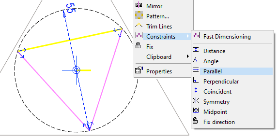
Set the top line of the triangle horizontal
-
Ribbon funcktion: Add parallel Constraint.
-
Click the top line of the triangle, figure 1).
-
Click the horizontal line of the center cross, figure 2).
-
Click the top line of the triangle.
-
Hold down the Ctrl key and click the horizontal line of blue cross.
-
Right-click function: Constraints > Parallel.
Stop sketching and create a Cutout Extrusion
-
Click OK on either the ribbon or the Right-click menu.
-
The Extrusion Details menu is opened.
-
Select: Cutout and Extrude.
-
Select: Thru All.
-
OK.
-
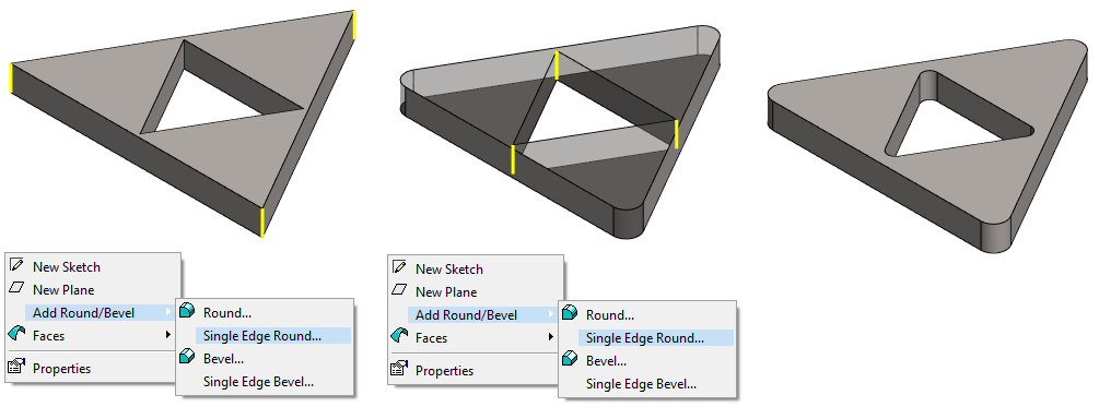
If you want to round the sharp corners of the model, it is easier to do it in the modeling mode.
-
Sketch remain simpler and thus easier to edit.
-
Roundings can be hidden if necessary (If the model needs to be lightened)
Rounding:
-
Select all corners of the same rounding at once (Remember Ctrl key to keep the selections)
-
Right-click function: Add Round/Bevel > Single Edge Round.
-
Two separate roundings have been made in the right figure.
Save the model
-
File > Save or click


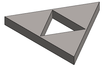
Further processing of the model (covered in other exercises)
You can add a material item to the model with the right-click function Item Data.
-
These will also appear in the parts list of the model drawing.
You can create a drawing for the model:
-
In the feature tree, select Drawings.
-
Right-click function: New Drawing.
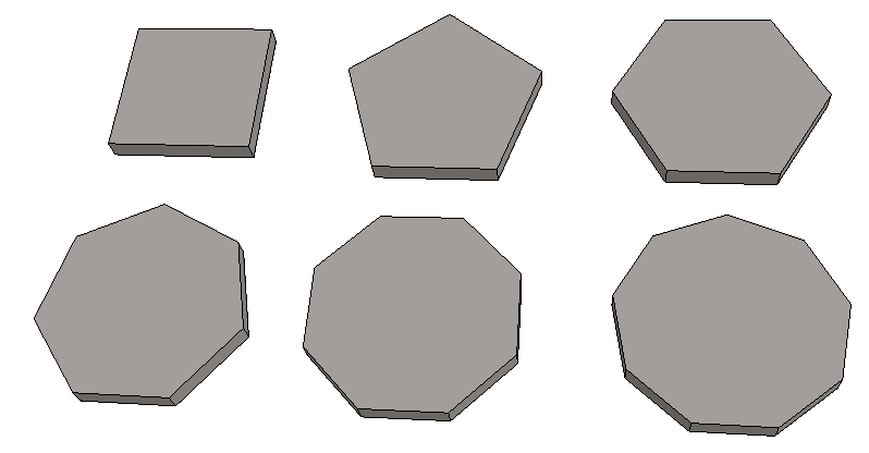
Examples of polygons
-
4 .... 9 corners
Download the Triange model here (VX_LN2.vxz)