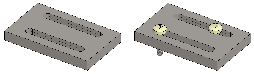
Exercise 3: Collar
This exercise was carried out with version 27.0 (Vertex 2021).
In this exercise you will learn to
-
Use the Sketch Smart Line Chain tool.
-
Use the Sketch Offset tool.
-
How to use the Obround tool.
Functions to be used:
-
New Sketch > To horizontal (XY) plane.
-
Sketching: Smart line chain.
-
Sketching: Offset
-
Operation: Boss Extrusion.
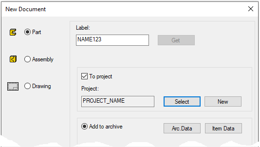
Create a new part
-
File > New > Part.
-
Enter the label (which is also the name of the model and by default will be the name of the drawing).
-
Enter the archive information by clicking Arc.Data.
-
Select the project for the model.
-
Select OK.
-
Draw an oval circle with a smart line chain.
-
Create a sketch horizontally: New Sketch > To horizontal (XY) plane.
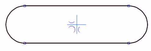
Draw a line chain symmetrically around the origo (blue cross):
Applications
The Smart Line Chain should be used when sketching a shape with both segment and arc of a circle. Thesegments and arcs are connected tangentially or perpendicularly. The program also assists to draw the oval symmetrically to the origo.
Assisting symbols
The following symbols are shown, when you click the cursor:
-
X- and Y-direction are locked (As with other line drawing functions).
-
Perpendicularity

-
Symmetry to the origo

-
Tangentiality

-
Horizontal locking

-
Vertical locking
-
Vertical or horizontal locking to the arc to be drawn

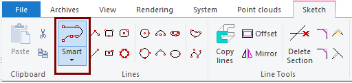
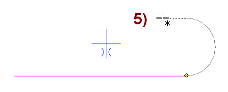
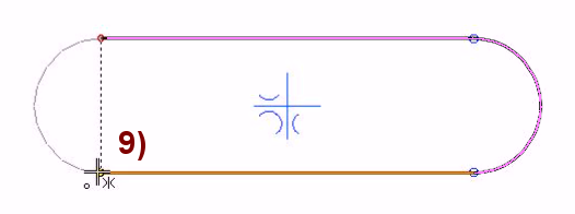
Click Ribbon function: Smart Line Chain
-
Click the starting point, in Figure 1).
-
Orientate the cursor horizontally to see a suggestion for X-direction locking, in Figure 2).
-
Click the cursor to lock the landscape direction.
-
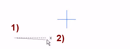
Move the cursor to the left until the symmetry symbol (
-
Click the cursor, and the program draws the endpoint of the line. The endpoints are symmetric to the origo.
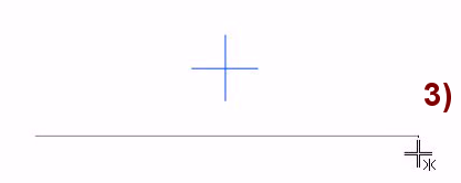
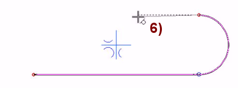
Move the cursor so that the program suggests drawing a tangential arc, and move the cursor up so that the program draws a guide line and suggests a perpendicular (
-
Click the cursor to lock the direction.
-
Tangential arc.
-
A line perpendicular to the previous line.
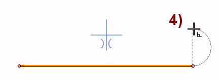
Move the cursor up until the program suggests a symmetrical (
-
Click the cursor to lock the symmetry.
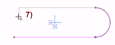
Move the cursor to the left until the program suggests a tangential line to the arc (
-
Click the cursor to lock the direction.
Move the cursor to the left until the program suggests a symmetrical drawing (
-
Click the cursor, and the program draws the endpoint of the line. The endpoints are symmetric to the origo.
Move the cursor so that the program suggests drawing a tangential arc, and move the cursor down so that the program draws a guide line and suggests a drawing perpendicular to it. (), in Figure 8).
-
Click the cursor to lock the direction.
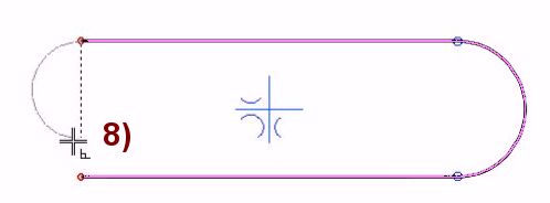
Move the cursor down until the program prompts you to select a line and its end point ( 
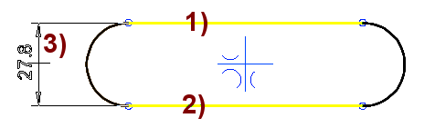
Dimension the sketch
-
Select function: Distance.
-
Click to the first line, in figure 1).
-
Click to the second line, in figure 2).
-
Select the location of the dimension, in figure: 3).
-
Enter the correct value: 30.
-
Click the first line, in figure 1).
-
Hold down the Ctrl key and select the other line in figure 2).
-
Select the location of the dimension, in figure 3).
-
Enter the correct value.
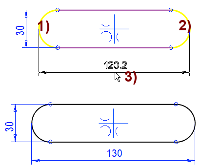
In the same way you can dimension the distance between the arcs.
-
Function: Distance.
-
Click to the first arc, in figure 1).
-
Click to the second arc, in figure 2).
-
Select the location of the dimension, in figure: 3).
-
Enter the correct value: 130.
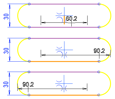
After selecting two arc lines or a circle line, the program suggests four different dimensioning options.
-
The options depend on the cursor position.
-
Move the cursor to a location that allows you to dimension the desired dimension.
Draw a parallel line
-
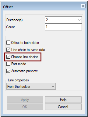
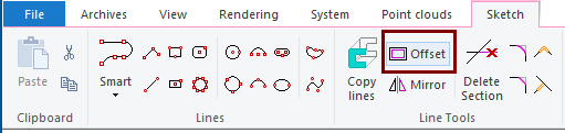
Select function: Offset.
-
Enter the distance of the lines: 2.
-
Select an option; Choose line chain.
-
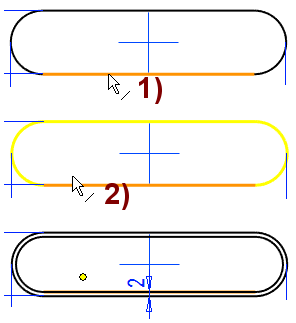
Click to the line, in figure 1).
-
Select in the direction in which the offset line is drawn, in figure 2).
-
Click OK.
The parallel copy lines of the lines can be drawn in many ways. See the Vertex on-line help for more information of the different options.
-
Distance(s) = You can enter one or more comma-separated dimensions to get multiple offset lines.
-
Count = You can only enter a number if you entered one distance.
-
Offset to both sides = The program draws offset lines on each side of the line selected.
-
Line chain to same side = Keep this option turned on, otherwise offset lines can be drawn on different sides of the parent lines.
-
Choose line chains = If another line is connected to the end of the selected the program selects all lines.
-
Fast mode = The offset is drawn immediately to the side where the cursor was when you selected the line
-
This reduces one click (Offset line side)
-
-
Automatic preview = The offset lines are drawn without pressing the Apply button.
Do the cutout extrusio
-
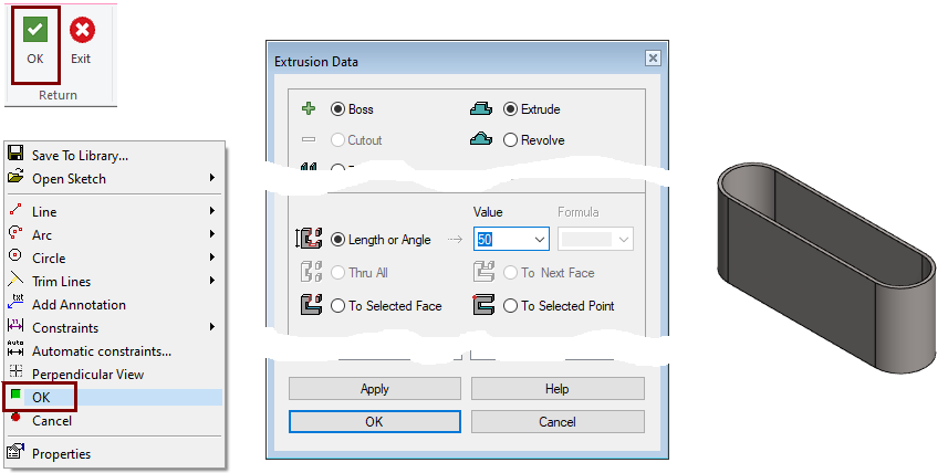
Stop sketching (

-
Select Boss and Extrude.
-
Enter the length of the part in the Value field: 50.
-
Click OK.
Save the model
-
File > Save or click


Further processing of the model (covered in other exercises)
You can add a material item to the model with the right-click function Item Data.
-
Material is shown in the parts list of the drawing.
You can create a drawing for the model:
-
In the feature tree, select Drawings.
-
Right-click function: New Drawing.
Obround
-
Select function: Obround
-
Select the first point, in figure 1).
-
Lock the direction if necessary by clicking the cursor.
-
Select the second point, in figure 2).
-
Select the width by clicking the cursor, in figure 3).
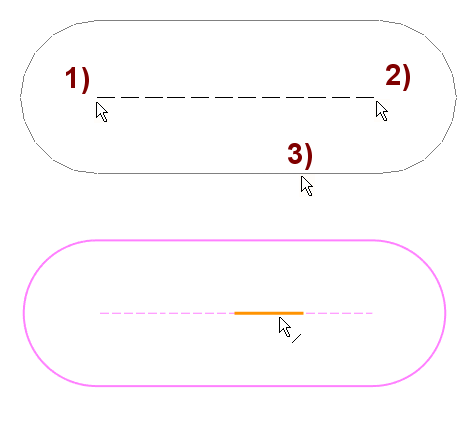
A guide line in the middle consisting of four segments. These segments can be later used to position parts.