

Exercise 1: Front plate
This exercise was carried out with version 27.0 (Vertex 2021).
General information
You can begin part modeling in the following ways:
-
Create a new part with archive data and sketch the first feature.
-
Create a new part with the archive data and read a feature from the feature library as a base.
-
Create a new part in an assembly and use the geometry of other parts in the assembly to model the new part.
You can sketch
-
To the part model base planes (XY, XZ and YZ planes).
-
To the face of a part.
-
To the line of a part.
-
To a three-point plane.
-
To a plane that is parallel or at an angle to a selected surface, or freely to a plane.
-
Parallel to a plane passing through a selected point.
-
To the auxiliary geometry of another part in an assembly (face, line, 3-point plane).
In this exercise you will learn to
-
Start a new model.
-
Sketch to an auxiliary plane and to a face of a part.
-
Draw a sketch and add geometric constraints.
-
Perform Boss Extrusions and Cutout Extrusions.
-
Edit a model by editing a sketch or an extrusion.
Functions to be used:
-
New Sketch > Auxiliary plane
-
New Sketch > Face
-
Sketching: Two point rectangle
-
Sketching: Circle
-
Sketching: Mirror
-
Sketching: Coincident constraint
-
Sketching: Distance and Diameter constraint
-
Operation: Boss > Extrude
-
Operation: Cutout > Extrude
-
Sketch: Edit
-
Extrusion: Edit operation
Front plate
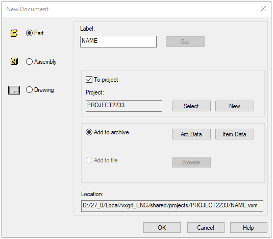
Create a new part
-
File > New > Part
-
Enter the label (which is also the name of the model and by default will be the name of the drawing).
Archive data
-
Enter the archive information by clicking Arc.Data.
-
The archive information of the model is copied to the drawing archive and will later appear in the drawing title bar.
Connect the part model to a project
-
You can create a new project by clicking New or select an existing project by clicking Select.
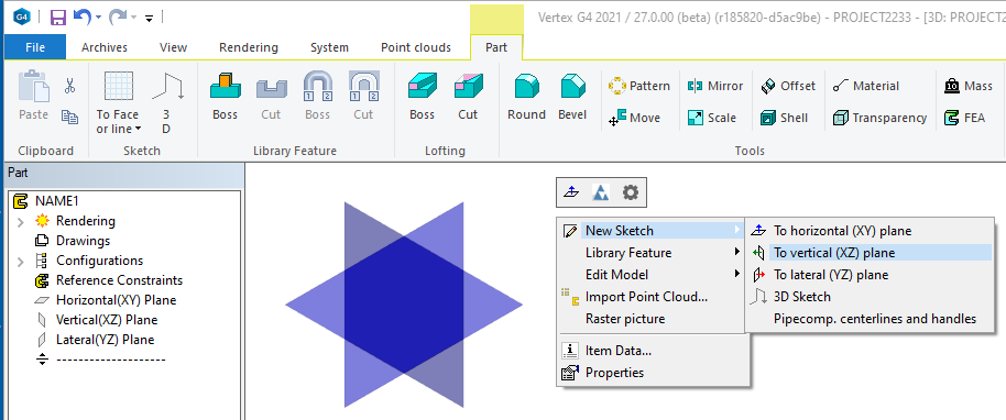
Start sketching
-
New Sketch > To vertical (XZ) plane
-
Alternatively, you can select an auxiliary plane and the context-sensitive function New Sketch > Face.
The model has three auxiliary planes.
-
To hide a plane, select it in the feature tree and select the context-sensitive function (right-click): Hide.
-
To restore a plane, select it in the feature tree and select the context-sensitive function (right-click): Restore.
-
You can show and hide the reference geometry and the auxiliary planes by pressing the G key or by selecting the Show Reference Geometry function on the tool strip:
-

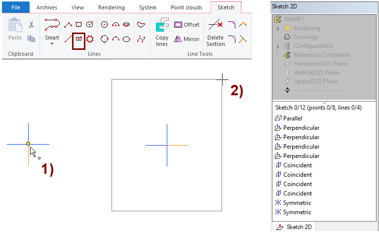
Draw a rectangle
-
The function: Two point rectangle.
-
Click the origo as the first point (center of the blue cross), in the figure 1).
-
The part becomes symmetrical with respect to the central cross. We will take advantage of this feature later.
-
-
Click the second point, in the figure 2).
In the beginning, it may be easier to draw a sketch if the sketch plane is perpendicular to you.
-
You get a perpendicular sketch when you have selected Perpendicular in the Settings group on the ribbon.
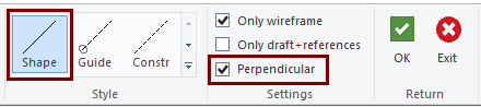
To draw a sketch, use the line style Shape.
-
Guide line is shown only in the sketch.
-
Construction line is shown as an auxiliary geometry, but it does not participate in the extrusion operation.
The program adds automatically constraints that limit the behavior of the geometry.
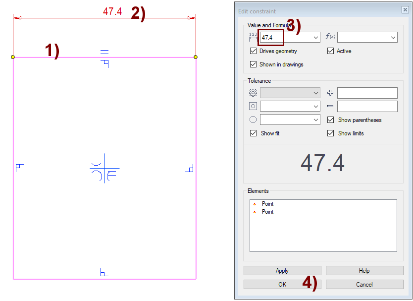
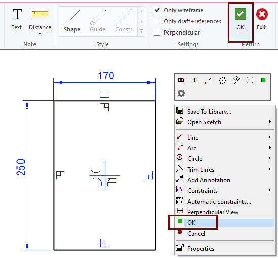
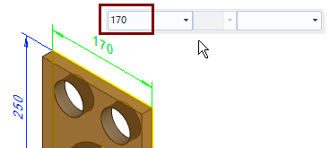
Add the first dimension of the sketch
The first dimension added to the sketch scales the entire geometry so that the relative distances between the elements in the sketch remain as you draw them.
-
The function: Distance.
-
Click the line to be dimensioned, in the figure 1).
-
Select the location of the dimension, in the figure 2).
-
The Edit Constraint dialog box opens.
-
-
Enter the correct value: 170, in the figure 3).
-
Accept the dimension constraint, press OK, in the figure 4).
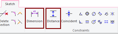
With the function Dimension, you click a single line, which gives the length of a segment, the radius of an arc, or the diameter of a circle.
With the function Distance, you always click two elements (lines or points).
-
If you click two lines, the program also turns the lines parallel.
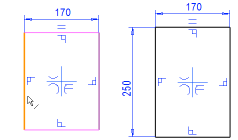
Add a vertical dimension to the sketch
-
Add a dimension for the vertical line.
-
Function: Dimension.
-
Click the line.
-
Select the location of the dimension.
-
Enter the correct dimension value: 250.
-
Stop sketching and move to the operation
-
Click OK on either the ribbon bar or in the context-sensitive menu.
-
The program opens the Extrusion Data dialog box.
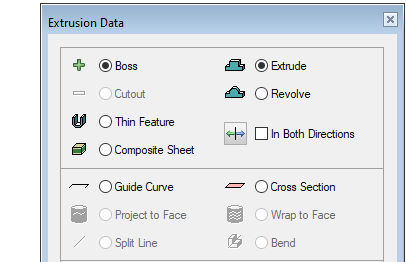
If you have sketched a shape that does not have open shape line ends, the program always suggests the Boss extrusion.
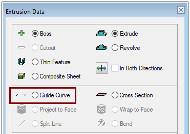
If your sketch has open ends of a shape line, the program suggests the Guide Curve operation, it means that Extrusion is not possible.
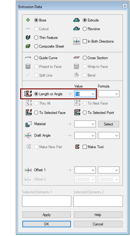
Enter the thickness (Extrusion length)
-
Make sure that the following options are selected in the Extrusion Data dialog box:
-
Boss.
-
Extrude.
-
-
Select Length or Angle as the operation.
-
Enter the thickness of the part in the Value field: 18.
-
-
Accept selections: OK.
After leaving the sketch, the part is still in the same position as you left it in the sketch.
-
On the left, the situation when the sketch has been perpendicular.
-
On the right, the Isometric View function has been used.
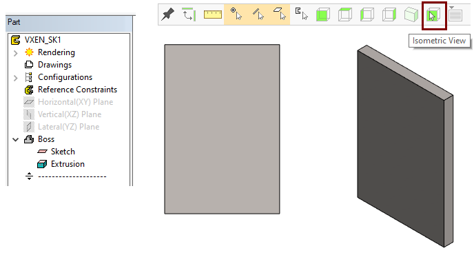

The tool strip has seven buttons that allow you to turn the model in specific directions.
-
Starting from left: front, top, left, right, isometric, select a surface that is rotated perpendicularly, and to the right is a list of projections where you can save your own directions.
By holding down the middle mouse button down you can rotate the model about the horizontal or vertical axis, depending on the movement of the cursor.
Shift + left mouse button => does the same thing as above.
Shift + right mouse button => zoom the model smoothly (more smoothly than with the mouse wheel, which causes jerky movement).
Shift + middle mouse button => pan and move sideways and vertically without rotating.
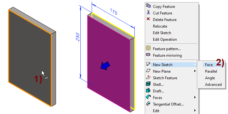
Start sketching the holes in the front plate
-
Click the face of the part, in the figure 1).
-
Right-click function: New Sketch > Face, in the figure 2).
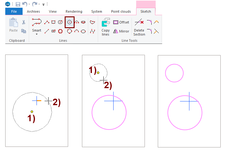
Draw two circles
-
The function: Circle with Center and Radii Point.
-
Select the location of the center of the circle, in the figure 1).
-
Select the location of a point on the circumference of the circle, in the figure 2).
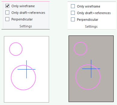
You can sketch in the shaded mode or in the wireframe mode.
Define the position of the center point of the lower circle with respect to the center cross
-
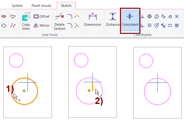
The function: Coincident.
-
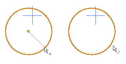
Click the center point of the circle, in the figure 1).
-
Click the vertical line of the center cross, in the figure 2).
-
As a result, the center point of the circle moves to the line of the vertical axis of the center cross.
-
-
The center point of the circle is selected if the cursor is inside the circle (there is a dot symbol in the lower right corner of the cursor).
-
The circumference of the circle is selected if the cursor is outside the circle (there is a line symbol in the lower right corner of the cursor).
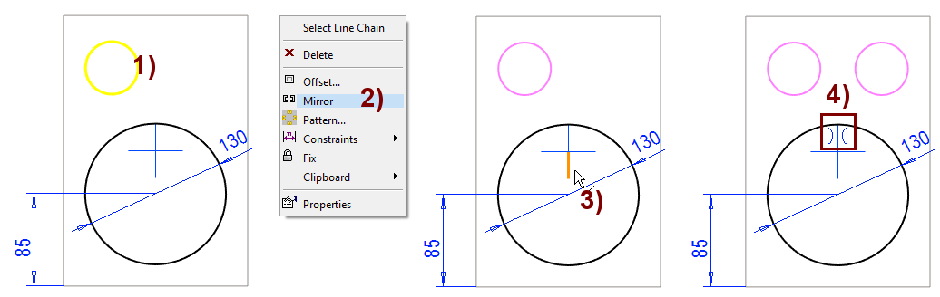
Define the diameter and the distance of the lower circle from the bottom
-
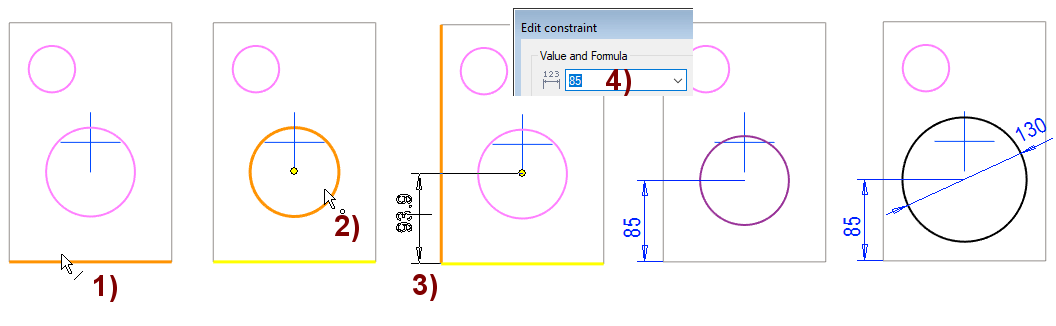
The function: Distance.
-
Click the line at the bottom of the front plate, in the figure 1).
-
Click the center point of the circle, in the figure 2).
-
Select the location of the dimension, in the figure 3).
-
Enter the correct value: 85, in the figure 4).
-
The function: Diameter.
-
Click the circle (circumference).
-
Select the location of the dimension.
-
Enter the correct value: 130.
Mirror the upper circle with respect to the central cross
-
Click the circle (when no activity is in progress), in the figure 1).
-
Right-click function: Mirror, in the figure 2).
-
Click the vertical line of the center cross as the mirror axis, in the figure 3).
-
The program mirrors the circle and sets the symmetry constraint to it, in the figure 4).
-
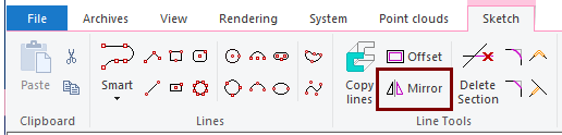
You can also mirror geometry with the ribbon function: Mirror.
-
Start the function: Mirror.
-
Click the geometry to be mirrored.
-
Click the axis of symmetry.
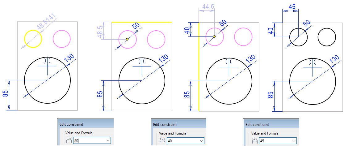
Dimension the other upper circle
-
Enter the diameter of the circle: 50.
-
Enter the distance from the top: 40.
-
Enter the distance from the edge: 45.
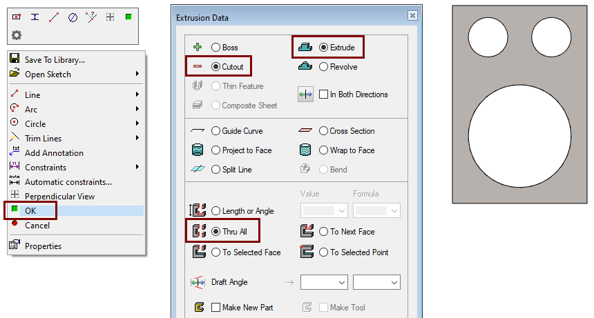
Perform the cutout extrusion operation
-
Stop sketching (

-
Select: Cutout and Extrude.
-
Select: Thru All.
-
Click OK.
For cutout extrusion, you can adjust the length of the extrusion:
-
Length or Angle: Enter a dimension.
-
Thru All: Extruded through the piece (even if the thickness changes).
-
To Selected Face: Click the surface to which the extrusion extends.
-
To Next Face: The extrusion stops at the next surface that the extrusion completely penetrates.
-
To Selected Point: Extrusion extends to the selected point.
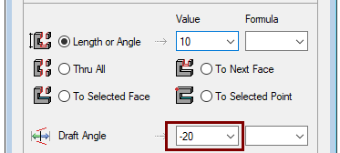
-
You can also enter a draft angle.
-
Negative angle constricts the extruding shape.
-
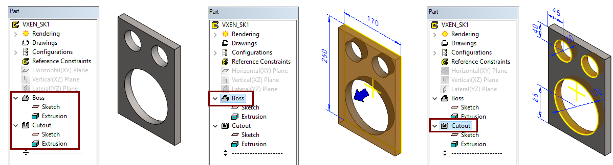
View and edit the history of a part
-
In the feature tree you will see the steps Boss and Cutout.
-
These features are divided into sketch and extrusion.
In the feature tree, select the feature or the sketch or extrusion associated with the feature.
-
The program shows the dimensions of this feature.
-
You can double-click a dimension to edit it.
-
You can also click the dimension once to show a mini toolbar that allows you to change the value of the dimension.
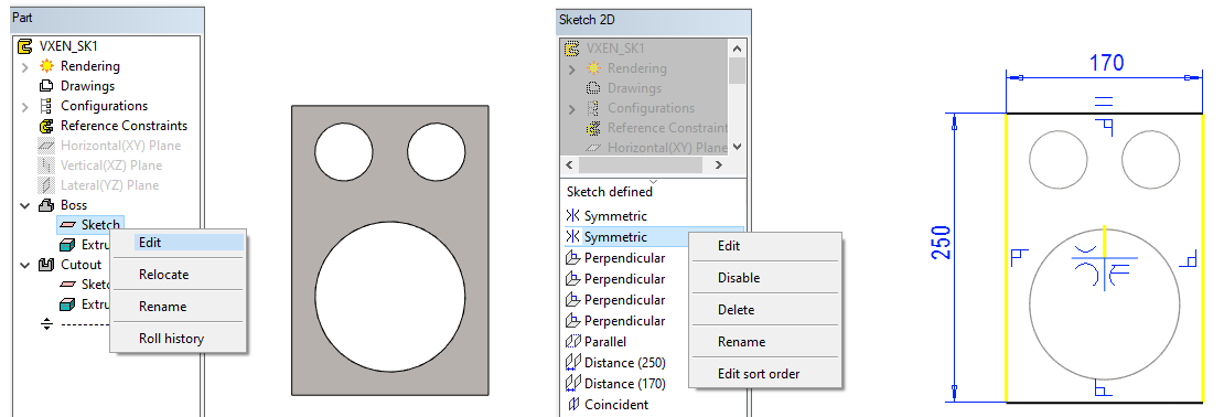
Edit the sketch
You can edit the sketch (add, delete, and change lines and constraints):
-
Double-click the sketch step in the feature tree.
-
In the feature tree, select the sketch step and the context-sensitive function Edit.
Below the feature tree, you can see the constraints that were created during the drawing of the sketch and defined by yourself.
-
Select a constraint.
-
Open the right-click menu.
-
Among other things, you can delete a constraint, temporarily remove it from the solution, change a descriptive name for it, and edit the constraint (dimensions or elements participating in the constraint).
-
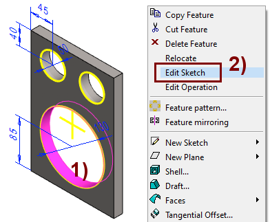
In the feature tree of a part model with many features, it can be difficult to find the feature that should be modified.
-
In this case, select a surface from the part, in the figure 1).
-
Right-click function: Edit Sketch, in the figure 2).
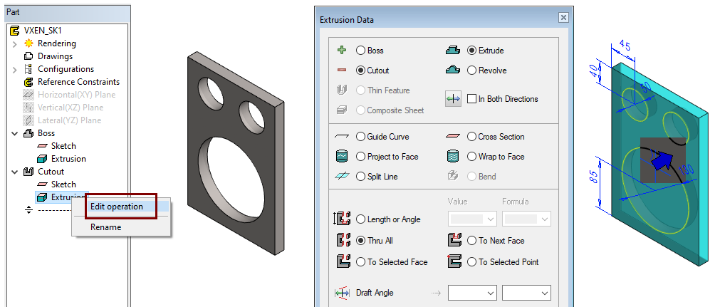
Edit operation (extrusion, etc.)
You can edit the extrusion:
-
Double-click the Extrusion step in the feature tree.
-
Select the Extrusion step and the right-click function: Edit operation.
If necessary, you can change:
-
Boss Extrude to Cutout Extrude or vice versa.
-
One operation to another:
-
Revolve
-
Guide Curve
-
Cross Section
-
Depending on the situation, also other operations
-
Save the model
-
File > Save or click


Further processing of the model (covered in other exercises)
You can add a material item to the model with the right-click function Item Data.
-
These will also appear in the parts list of the model drawing.
You can create a drawing for the model:
-
In the feature tree, select Drawings.
-
Right-click function: New Drawing.