

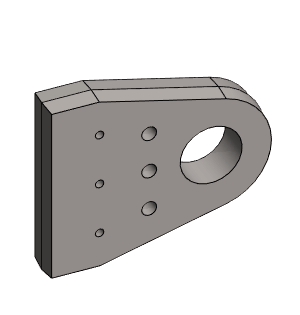
Exercise 8: Lug
This exercise was carried out with version 27.0 (Vertex 2021).
In this exercise you will learn to
-
Sketching.
-
Rounding lines in a sketch.
-
Changing line styles.
-
Adding a Cutout Thread feature, also by copying.
-
Select elements by fencing.
Functions to be used:
-
Sketching: Rectangle, Polyline, Two Point Line, Circle with Center and Radii Point.
-
Sketching: Round.
-
Sketching constraints: Dimension, Diameter, Coincident and Equal Radius.
-
Sketching: Line style: Rot.axis.
-
Sketching: Rotational pattern.
-
Operations: Boss Extrusion and Cutout Boss Extrusion.
-
Part: Library Feature > Cutout (Thread).
-
Sketching: Add Feature Copy.
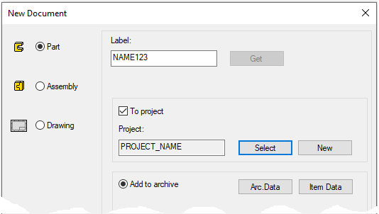
Create a new part
-
File > New > Part.
-
Enter the label (which is also the name of the model and by default will be the name of the drawing).
-
Enter the archive information by clicking Arc.Data.
-
Select the project for the model.
-
OK.
-
Start sketching
-
New Sketch > To vertical (XZ) plane
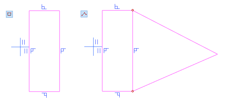
Sketch the geometry
-
Function: Rectangle, Polyline.
-
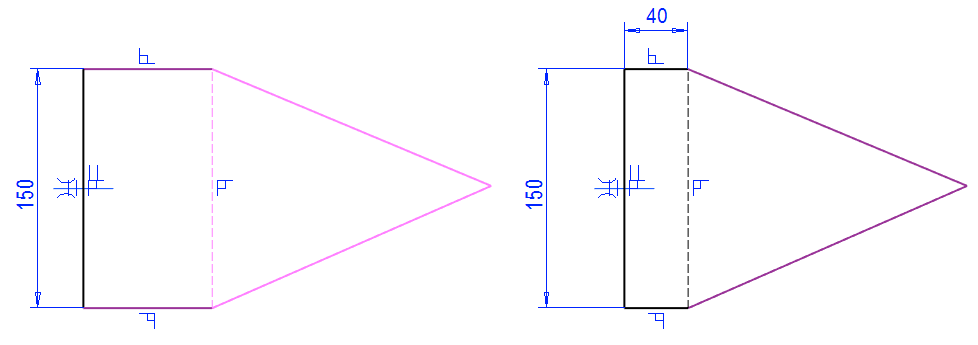
Sketch the rectangle vertically approximately symmetrically to the horizontal line of the origo.
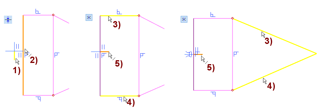
Add the Conincidet and Symmetry constraints
-
Function: Conincidet.
-
Click the vertical line of the center cross, in the figure 1).
-
Click the vertical line of the rectangle, in the figure 2).
-
Function: Symmetry.
-
Click the first line, in the figure 3).
-
Click the second line, in the figure 4).
-
Click the horisontal line of the center cross, in the figure 5).
Change shape line to a guide line and add the dimensions of the box
-
Click the vertical line on the right and change the style to be Guideline.
-
Function: Dimension or Distance.
-
Enter the height: 150.
-
Enter the width: 40.
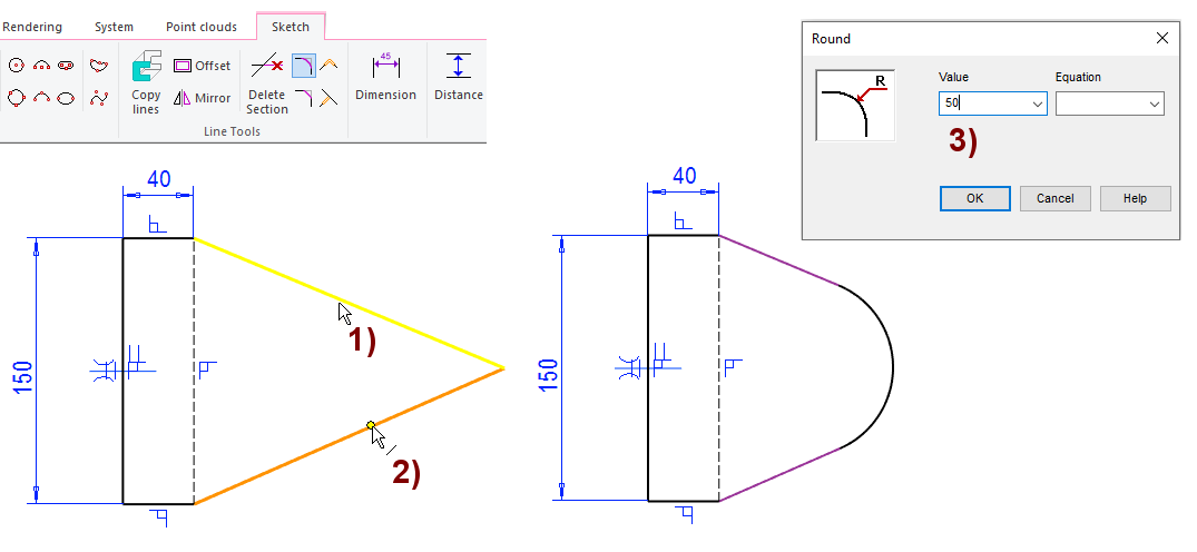
Add rounding to the sharp tip
-
Function: Round.
-
Click the first line, in the figure 1).
-
Click the second line, in the figure 2).
-
Enter the value of radius: 50, in the figure 3).
-
Click a point (at the junction of two lines)
-
Right-click function: Round.
-
Enter the value of radius.
Give the length to the lug
-
Function: Distance.
-
Click the left vertical line on the lug.
-
Click the circle arc (no midpoint - Note cursor attribute: line)
-
Select the location of the dimension.
-
Enter the value: 180.
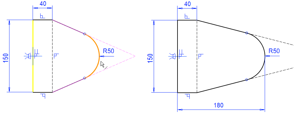
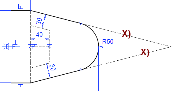
Draw and dimension four guide lines
These lines are later used to position the thread features.
-
Function: Polyline.
-
Function: Two Point Line.
-
Function: Distance.
You can delete the guide lines, in the figure X).
-
Guide lines only appear in the sketch, not in the model.
-
They have no operational significance in this sketch.
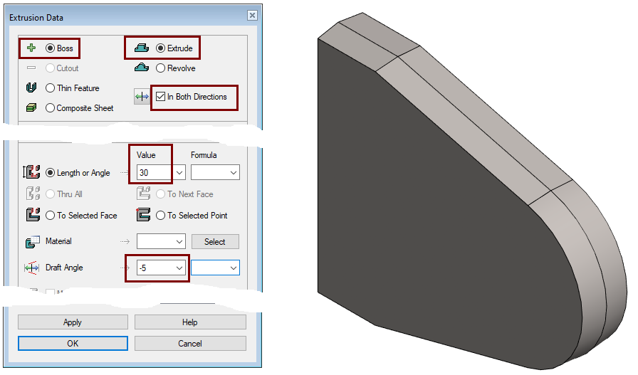
Perform the boss extrusion operation
-
Stop sketching (the green OK button).
-
Select: Bossand Extrude.
-
Select: In Both Directions. (Draft angle appears in both directions)
-
Enter the thickness of the part in the Value field: 30.
-
Enter the Draft Angle: -5. (negative value makes the part shrink relative to the sketch).
-
Click OK.
A negative Draft Angle value was used in the extrusion to obtain the Draft at the same time as the extrusion.
-
In the real part, there would be no Draft at the end of the lug.
-
Normally, the extrusion would be done without Draft Angle and the Draft should be done separately with respect to the Vertical (XZ) Plane. The end of the lug should not be chosen as the surface to be Draft.
Create a new sketch
-
Click the face of the part.
-
Right-click function: New Sketch > Face.
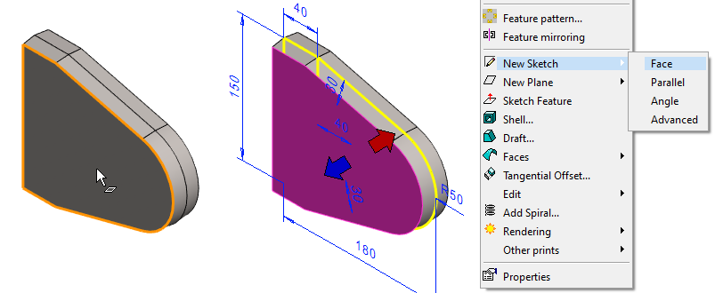
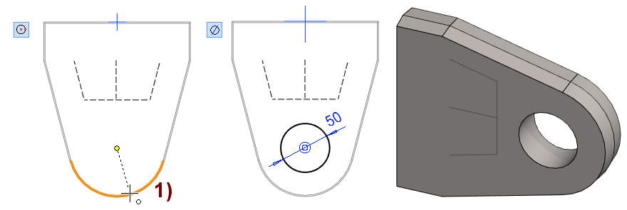
Sketch a hole and cutout extrude it through the part
-
Function: Circle with Center and Radii Point.
-
Click the center of the circle so that the cursor retrieves the point from the geometry of the part, in the figure 1).
-
Select the location of a point on the circumference of the circle.
-
-
Function: Diameter. Enter the value: 50.
-
Perform the cutout extrusion operation
-
OK.
-
Select: Cutout, Extrude and Thru All.
-
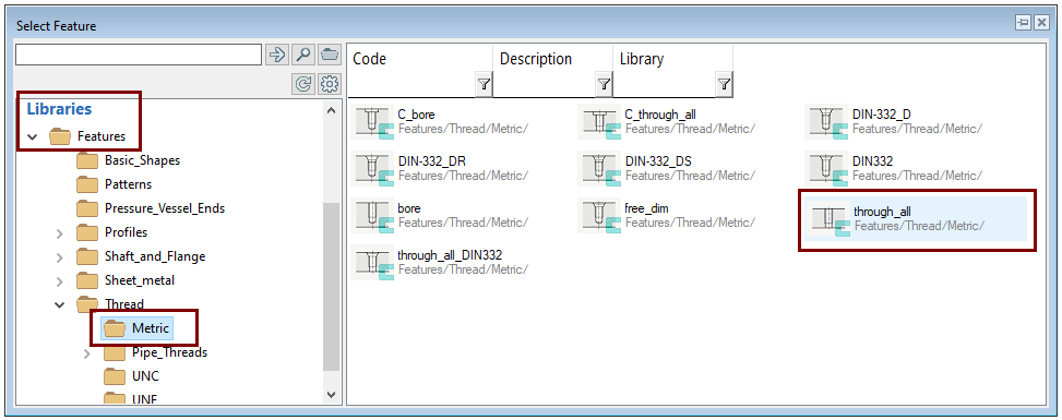
Add a cutout thread from the library
-
Function: Add cutout using feature from library

-
Or Right-click function: Library feature > Cutout
-
-
Find the library feature in the browser: Library > Features> Thread> Metric> through_all.
-
Open a universal browser: key B or File > Open
-
Browse the library and select a feature.
-
Give the dimensions you want.
-
Click it on the face of the part and place it with constraints.
-
Exit sketch (With the OK) => The operation is always: Library feature> Cutout.
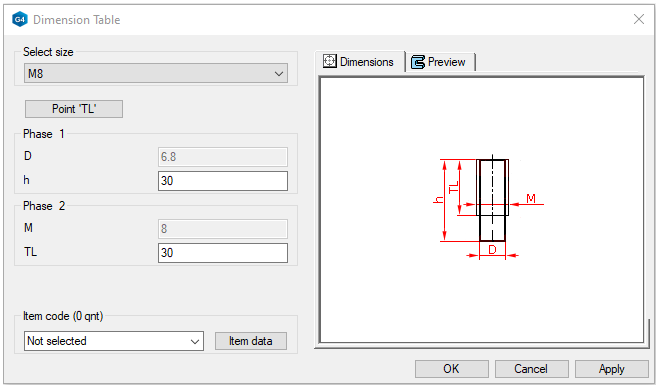
Give dimensions of the feature and add it to the surface
-
Select the size: M8.
-
Enter the hole length h: 30. (Because the thickness of the lug is 30mm.)
-
Enter the length of the thread section TL: 30. (The threading is extended through the part.)
-
Click the location of the feature on the side of the part.
-
Note that the direction of the feature changes as you move the cursor from one surface to another.
-
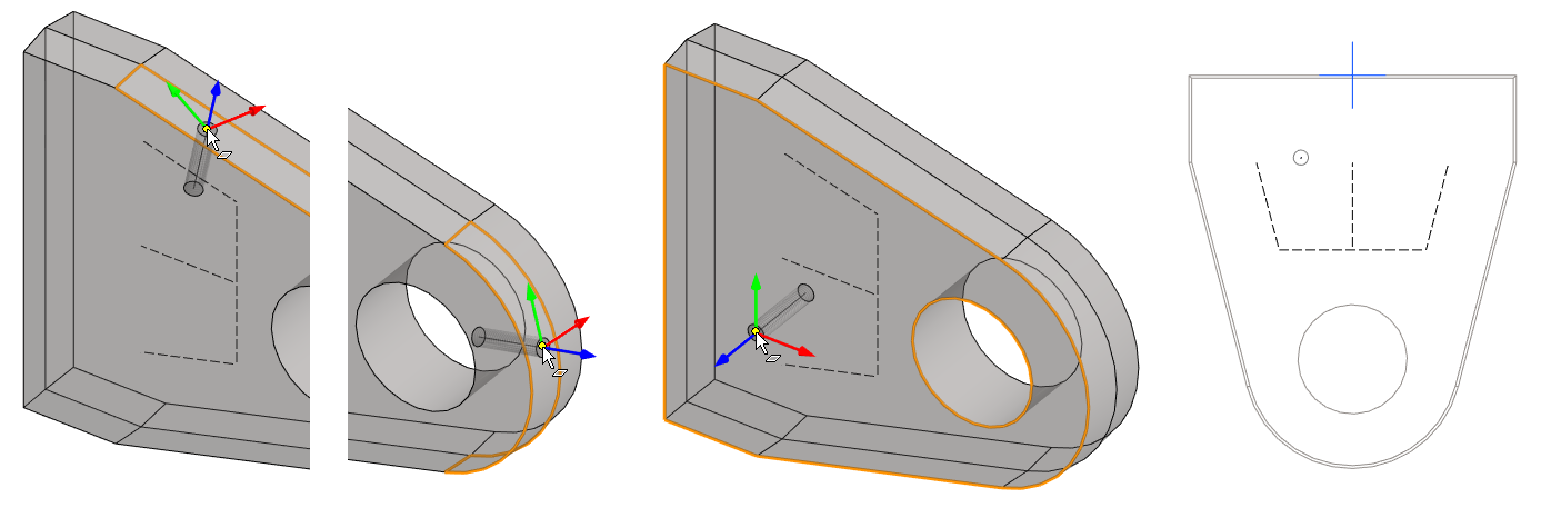
Add copies of the feature
-
Right-click function: Add Feature Copy.
-
Add a couple of copies, in figures 1) and 2).
In the figure 1) The feature is positioned at the endpoint of the guide line shown in the model, but note that a constraint of Coincident is not automatically added between the feature and the guide geometry.
-
The feature remains in place if the previous guide geometry does not change its position.
-
But if the previous feature is modified, then the feature does not follow the guide geometry.
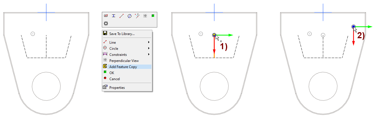
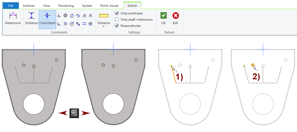
Bind the features in place
-
Function: Coincident.
-
Click the end point of the line from the guide geometry, in Figure 1).
-
Click the midpoint of the feature, in Figure 2). (The order in which the points are clicked does not matter).
-
Bind all three features with the coincident constraint to the points of the guide geometry.
-
Exit the sketch: OK.
The Sketch ribbon mainly has only sketch constraint functions when you are positioning a feature on the face of a part.
-
Line drawing functions, line tools, or text insertion are not available.
-
The right-click menu also includes drawing a guide line and copying the line (as a guide line) to the sketch.
Note that in shaded mode, the geometry behind the surfaces is always hidden.
-
The visibility of the guide geometry in the model depends on if you have shown or hidden the auxiliary geometry using key G.
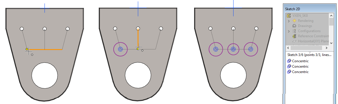
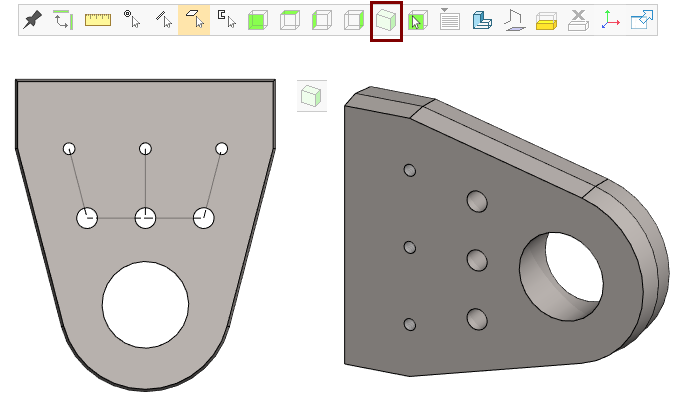
Sketch three circles on the face of the model
-
Click to the face on the side of the lug.
-
Right-click function: New Sketch > Face.
-
Function: Circle with Center and Radii Point.
-
Click the center of the circle so that the cursor retrieves the point from the geometry of the part.
-
Select the location of a point on the circumference of the circle.
-
The program now adds a concentricity constraint to the circle with the points of the guide geometry, so if the previous guide geometry changes, the circles will follow.
-
You can see this from the list of constraints below the feature tree.
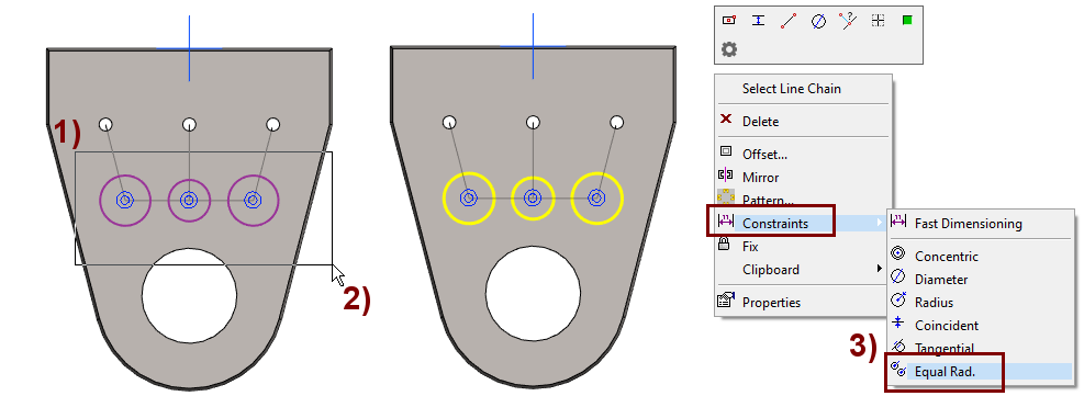
Give the Equal Radius constraint to the circles
First, the circles are selected by fencing them and then the Equal Radius constraint is given.
-
Select a point in space (while no function is in progress), in the figure 1) and hold down the mouse button.
-
Move the cursor so that the selected geometries remain inside, in the figure 2).
-
Release the mouse button. Now the elements are selected.
-
Right-click function: Constraints > Equal rad., in the figure 3).
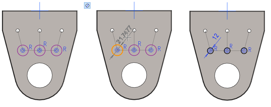
Give a diameter to one circle.
-
Function: Diameter.
-
Click the circle.
-
Enter the diameter of the circle: 12.
Perform the cutout extrusion operation
-
Stop sketching (the green OK button).
-
Select: Cutout and Extrude.
-
Select: Thru All.
-
Click OK.
Save the model
-
File > Save or click


Further processing of the model (presented in Exercise 5. Swivel lever)
You can add a material item to the model with the right-click function Item Data.
-
These will also appear in the parts list of the model drawing.
You can create a drawing for the model:
-
In the feature tree, select Drawings.
-
Right-click function: New Drawing.