

Exercise 10: Logo
![]()
![]()
This exercise was carried out with version 27.0 (Vertex 2021).
In this exercise you will learn to
-
Use formulas to help with dimensional variation.
-
Save the sketch to the sketch library.
-
To repeat: Boss Extrude and Boss Extrude.
-
Dimension Table
-
Dividing a surface into different surfaces.
Functions to be used:
-
Sketching: Two point rectangle, Polyline, Two Point Line.
-
Sketching: Mirror
-
Sketching constraints: Coincident, Distance, Angle and Coincident. (Other constraints: parallel, perpendicular and symmetry arise when drawing and mirroring sketch geometry)
-
Sketching: Fix and unfix
-
Sketching: Save to Library
-
Sketching: Open sketch from the Library
-
Operation: Boss Extrude and Boss Extrude.
-
Operation: Split line.
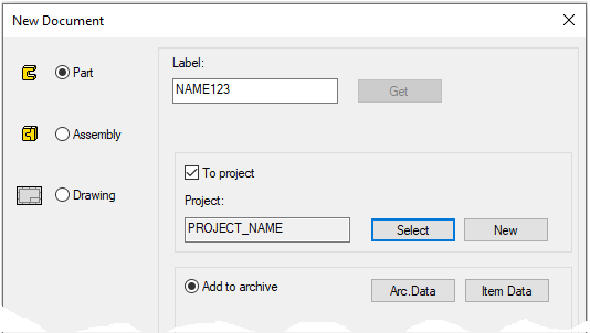
Create a new part
-
File > New > Part.
-
Enter the label (which is also the name of the model and by default will be the name of the drawing).
-
Enter the archive information by clicking Arc.Data.
-
Select the project for the model.
-
OK.
-
Start sketching
-
New Sketch > To horizontal (XY) plane
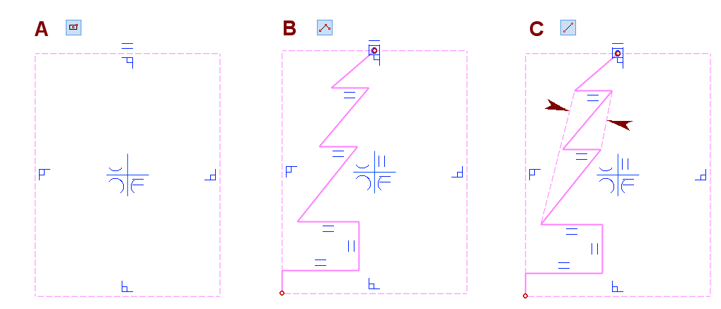
Sketch a rectangle, in the figure A.
-
Function: Two point rectangle
-
Line style: Constraint line.
-
Click the origo as the first point (center of the blue cross).
-
Click the second point.
Sketch the other side of the logo, in the figure B.
-
Function: Polyline.
-
Line style: Shape line.
-
Click the center of the top line.
-
Avoid 45-degree directional locks, but use vertical and horizontal locks.
-
Draw a half shape, but not the bottom horizontal line.
Sketch guide lines, in the figure C.
-
Function: Two Point Line.
-
Line style: Constraint line.
-
Sketch two segments from the endpoint to the endpoint.
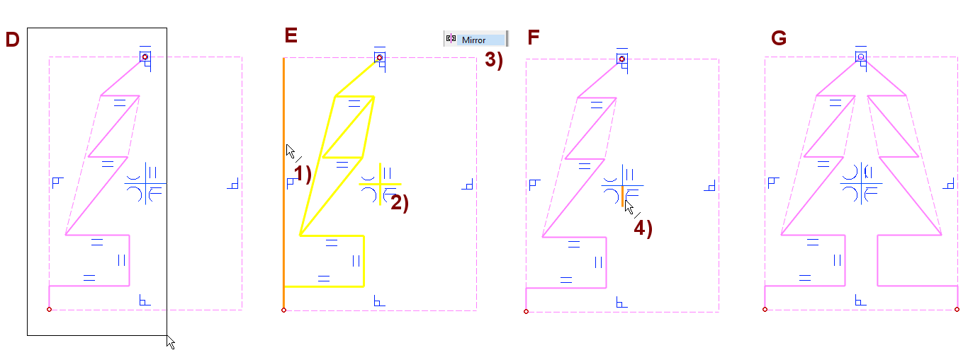
Mirror the sketch geometry
Select the geometry to be mirrored, in the figure D.
-
Fence the geometry.
-
The program marks the mirrored geometry with attention color (yellow).
Remove the left vertical line from the selection, in the figure E.
-
Hold down the Ctrl key and select the line, in the figure 1).
-
There is no need to care about the lines of the central cross, in the figure 2).
Copy the selected geometry by mirroring, in the figure F.
-
Right-click function: Mirror.
-
Click mirroring axis (vertical line of center cross).
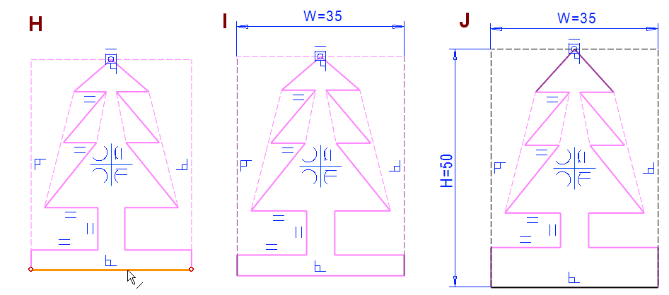
Change the style of the lowest horizontal line to a shape line
-
Click the line (when no activity is in progress), in the figure H.
-
Choose a line style: Shape.
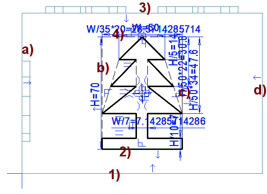
Enter the main dimensions and enter the variable ID
-
Function: Dimension (or Distance).
-
Click the line, in the figures I and J.
-
Select the location of the dimension.
-
Enter the value and Formula
-
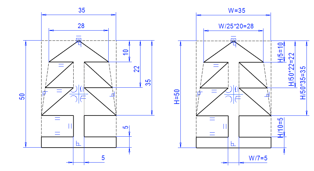
Enter on the horizontal line: 35 and W.
-
Enter on the vertical line: 50 and H.
-
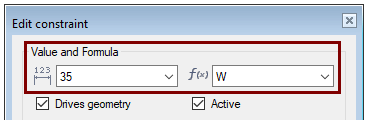
It is recommended that you use only uppercase letters in variable IDs.
-
In this case, they can be easily separated, for example, from the code of parametric programs
It is recommended that you use more than one letter in the variable IDs (unlike in this exercise).
-
This is because Vertex G4 uses some letters by default or programmatically in some sense (such as t, which is used to indicate the material thickness of sheet metal models).
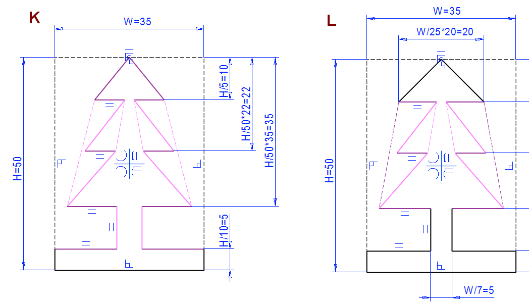
Enter Dimensions, also consider variables
Enter the vertically bound distance constraints and formulas as shown in the figure K.
-
10, formula: H/5.
-
22, formula: H/50*22.
-
35, formula: H/50*35.
-
5, formula: H/10.
Enter the horizontally bound distance constraints and formulas as shown in the figure L.
-
20, formula: W/35*20
-
5, formula: W/7
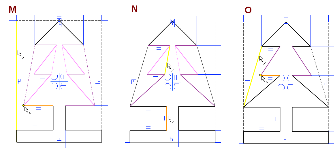
Add three Coincident constraints
-
Function: Coincident.
Coincident between line and point, in the figure M.
-
Click the line.
-
Click the point.
Coincident between line and line, in the figure M.
-
Click the first line.
-
Click the second line.
Coincident between line and point, in the figure O.
-
Click the line.
-
Click the point.
The sketch is defined.
-
No more purple lines.
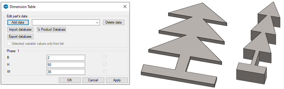
Test the variation of the sketch
-
Right-click function: Dimension Table.
-
Enter the values of the variables W and H.
If the sketch is not varied well, add constraints
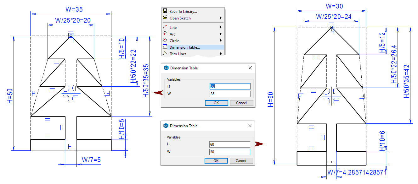
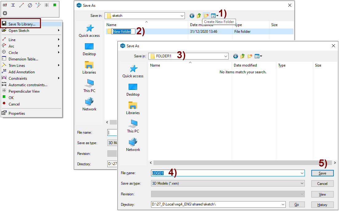
Save the sketch to the sketch library
-
Right-click function: Save To Library.
-
Select a folder or create a new folder.
-
It's a recommended to save sketch of the same type in the same folder.
-
-
Create a new folder, in the figure 1).
-
Enter a name to the folder, in the figure 2).
-
Select the folder, in the figure 3).
-
Enter the name for sketch, in the figure 4).
-
Save the sketch, in the figure 5).
Especially if multiple designers use the system, it's a recommended to think about the names of the folders under the sketch library so that other designers can find general-purpose sketches.
-
In addition, each designer should create their own folder, maybe with the designer's name, in which the designer can save their own temporary sketches.
-
In the name of the sketch folder, it is not advisable to use Scandinavian letters (Like ÄÖÅ, äöå) or other special characters, because in this case the designer, who has a completely english-speaking environment can not see that kind of folder.
The sketches are saved below the folder vxg4/shared/sketch or vxg4_srv/shared/sketch.
-
Unlike models and drawings, sketches can also be dragged from one Folder to another using Windows File Explorer (Results are displayed when the Vertex is restarted or the browser is refreshed).
-
If you want to move sketches to another folder, be sure to copy the file itself (.vxm) and its browse image (.jpg), e.g.
-
LOGO1.vxm
-
LOGO1.jpg
-
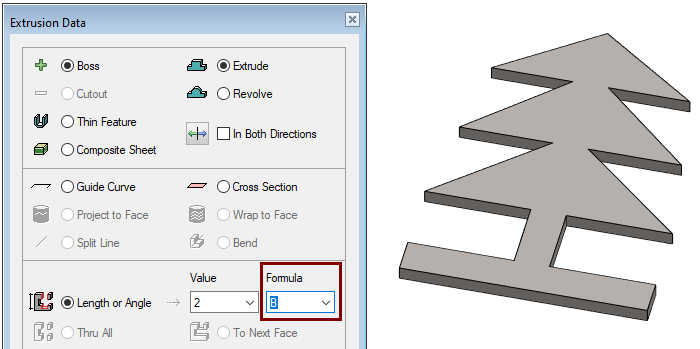
Perform the boss extrusion operation
-
Stop sketching (the green OK button).
-
Select: Boss and Extrude.
-
Select: Length or Angle.
-
Enter the value: 2.
-
Enter the formula: B.
-
Click OK.
Test the variation of the model
-
Right-click function: Dimension Table.
-
Enter the values you want.
Save the model
-
File > Save or click


Test a libraryed sketch
Create a new part
-
File > New > Part.
-
Enter the label (which is also the name of the model and by default will be the name of the drawing).
-
Enter the archive information by clicking Arc.Data.
-
OK.
-
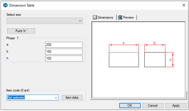
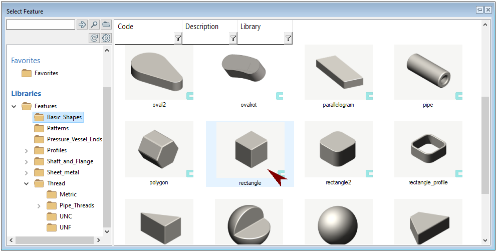
Read a feature from the library
-
Function: Library Feature > Boss.
-
Select a feature: Features > Basic_Shapes > rectangle.
-
Enter the required dimensions: 200, 150 and 100.
-
OK.
-
-
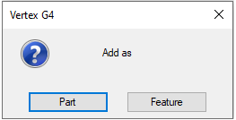
Select: Feature.
As part of:
-
The original history of the feature is shown in the feature tree.
-
If necessary, you can change all history stages and their sketches individually.
-
You can also remove features from the history tree that you don't need.
As feature of:
-
The imported feature appears in the history tree of a part as only one history step.
-
You can only edit it using the dimension table saved in the feature.
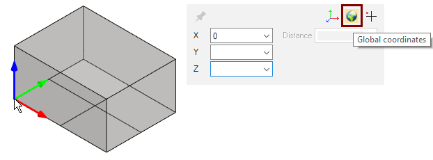
Position the corner of the feature at the origo of the model
-
The feature is attached to the cursor at its corner.
-
The feature can be placed anywhere, but it would be better if the corner of the feature were located at the origo of the model.
-
Place the corner at the origo:
-
Press the number key: 0.
-
Click: Global coordinates.
-
Press: Enter.
-
When the part is later placed in the assembly, the cursor is attached to the origo of the part.
-
Therefore, it is good if the origo of the part is located in a reasonable place in relation to the geometry of the part.
-
Of course, the placement point can be changed when a part is added to the assembly.
Select the front surface and do sketch in it
-
Choose an isometric projection.
-
Click to the front face.
-
Right-click function: New Sketch > Face.
Read the sketch and position it
-
If the sketch or folder you have created does not appear in Sketches > Own, update the browser with the Right-click function: Refresh Browser.
-
Select the sketch you saved and place it.
-
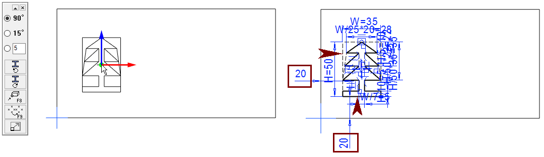
Position the sketch with two Distance conditions, 20, as shown in the figure right.
A menu appears in the upper left corner of the desktop, allowing you to (top to bottom):
-
Choose a swivel angle of 90 degrees, 15 degrees. or the angle of the angle you entered.
-
Turns the sketch counterclockwise (by the above angle).
-
Turns the sketch clockwise (by the above angle).
-
Click the focus point of the sketch. (Also with the F8 function key).
-
Mirror the sketch. (Also with the F9 function key).
-
Scale the sketch.
Perform the cutout extrusion operation
-
Stop sketching (the green OK button).
-
Select: Cutout and Extrude.
-
Select: Length or Angle.
-
Enter the value: 5.
-
Click OK.
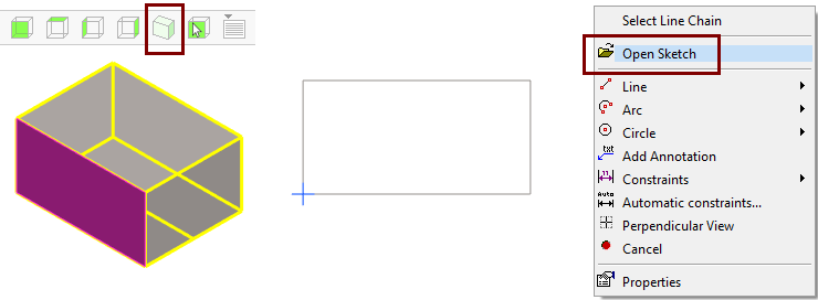
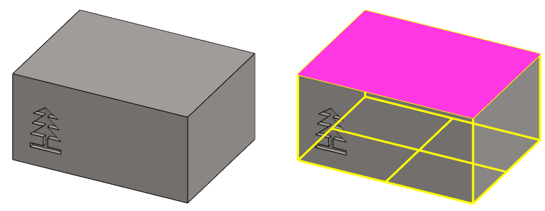
Create a sketch on the top surface
-
Click the top face.
-
Right-click function: New Sketch > Face.
Add a sketch logo for the first time
-
Right-click function: Open Sketch.
-
Read the sketch, turn it 90 degrees counterclockwise and put it in place.
-
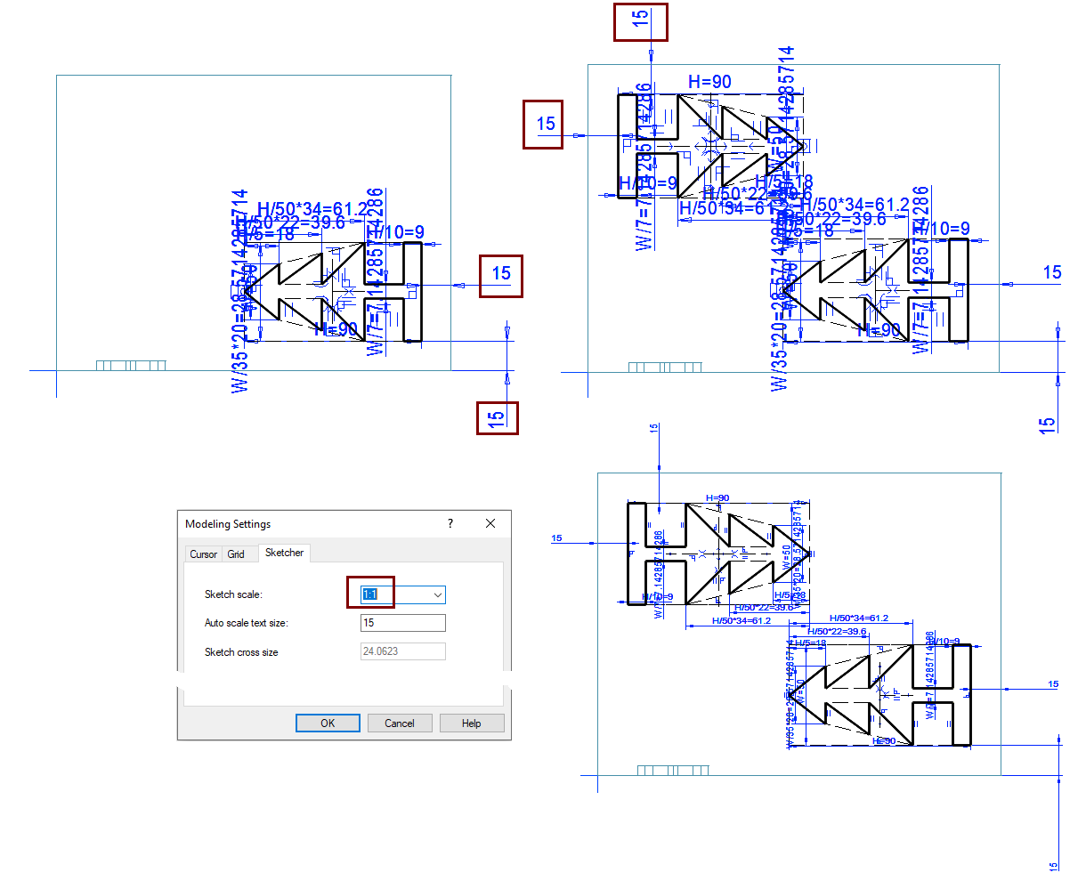
Resize the sketch with the dimension table: H 90 and W 50.
-
Position the sketch with two Distance conditions, 15, as shown in the figure right.
Add a sketch logo for the second time
-
Right-click function: Open Sketch > Add.
-
Read the sketch, turn it 90 degrees clockwise and put it in place.
-
Resize the sketch with the dimension table: H 90 and W 50.
-
Position the sketch with two Distance conditions, 15, as shown in the figure right.
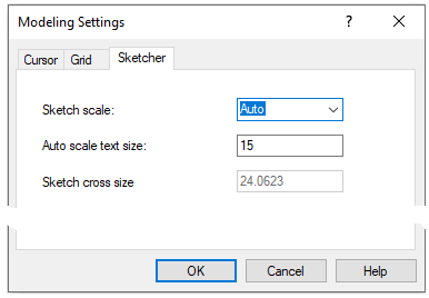
The geometry of the sketch dimensions and the size of the center cross automatically scale according to the size of the sketch.
You can influence these with the Right-click function in the sketch: Properties.
-
Sketch scale: Auto (automatically scalable dimensions and center cross) or selected scale.
-
Auto scale text size: When automatic text and size scaling is selected, you can use this value to specify the relative size of the text.
-
Sketch cross size: You can only adjust the size when you have selected a fixed scale as the sketch scale.
Perform the boss extrusion operation
-
Stop sketching (the green OK button).
-
Select: Boss and Extrude.
-
Select: Length or Angle.
-
Enter the value: 4.
-
Click OK.
Create a sketch on the top surface
-
Click to the right end face.
-
Right-click function: New Sketch > Face.
Read the sketch and place it in the middle of the face
-
Right-click function: Open Sketch.
-
Place a sketch.
-
Resize the sketch with the dimension table: H 70 and W 50
Place the sketch in the center.
-
Positioning is possible with either the Equal Distance or Centering constraint.
-
Function: Equal Distance.
-
Click the lines, in the figure 1), 2), 3) and 4). (Model borders and sketch guide lines)
-
Click the lines, in the figure a), b), c) and d). (Model borders and sketch guide lines)
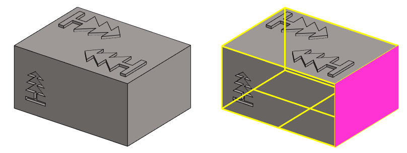
Perform the split Line operation
-
Stop sketching (the green OK button).
-
Select: Split Line.
-
Click OK.
This operation divides the surface into two surfaces. As long as the line either delimits the surface into two areas or cuts the surface in half.
-
If necessary, you can also share other "behind the sketch" surfaces in the dividing line if you select other surfaces in the action dialog.
This operation adds sketch geometry to the surface as guide lines. These can later be used to make a new sketch. As was done in Exercise 9. Seal
The guide lines can have their own meaning when the parts are placed together in the assembly.
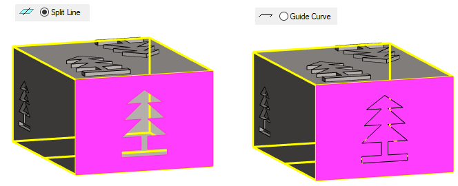
If you want to change the action to another (for example, a Split Line line to Guide Curve):
-
Select the action in the part of the history tree.
-
Right-click function: Edit operation.
-
Select another operation.
-
OK.
Save the model
-
File > Save or click
Change the dimensions of the part
-
Right-click function: Dimension Table.
-
Enter the values you want.
-
You will notice that the dimensions of all logos change at once.
-
You can undo your dimensional changes with Undo:


If you need to use the same formula-controlled sketch in the same part in multiple places but with different dimensions, then you can "passivate" the sketch formulas in the following three ways:
Delete the contents of the formula field:
-
Add a sketch and place it first.
-
Edit each dimension with a formula and delete the contents of the Formula field.
Rename variable:
-
Add a sketch and place it first.
-
Edit each dimensions with a formula and change the variable ID in the Formula field.
Fix the geometry of sketch:
-
Select (eg by fencing) the geometry of the sketch.
-
Right-click function: Fix.
-
After this, the lines are black and the dimensions are red, i.e. they are overdefined and no longer vary.
-
To edit the Fixed geometry, select the geometry and use the right-click function: Release.
![]()
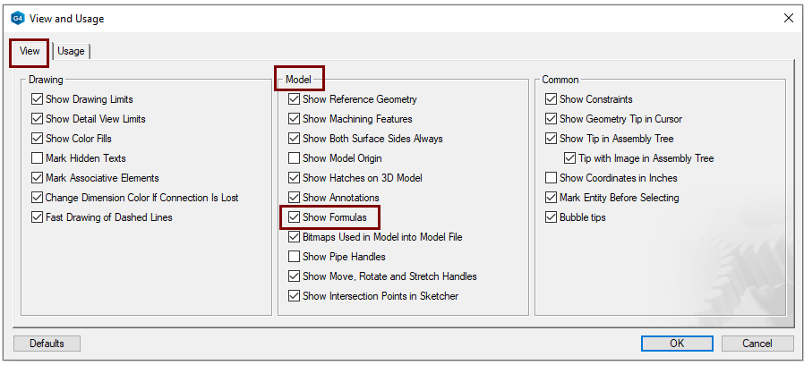
You can influence the appearance of formulas in sketching with the setting:
-
File > User Preferences > Drawings, Models> View > Model > Show Formulas
Save the model
-
File > Save or click
Further processing of the model (presented in Exercise 5. Swivel lever)
You can add a material item to the model with the right-click function Item Data.
-
These will also appear in the parts list of the model drawing.
You can create a drawing for the model:
-
In the feature tree, select Drawings.
-
Right-click function: New Drawing.