

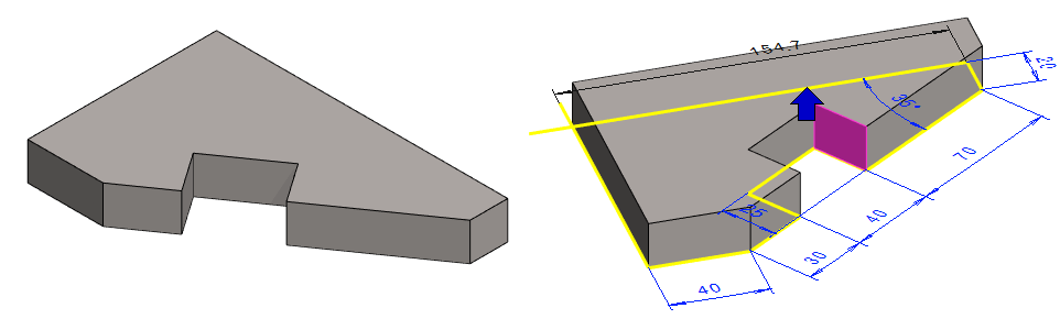
Exercise 4: Corner piece
This exercise was carried out with version 27.0 (Vertex 2021).
In this exercise you will learn to
-
Use sketching tools Coincodent, perpendicular, angle, distance and centering.
-
Use dimensions which are not constraints.
-
Extruse the part in both directions.
-
Hide and show constraints: F9.
-
Undo.
Functions to be used:
-
New Sketch > To horizontal (XY) plane.
-
New Sketch > Face.
-
Sketching: Polyline
-
Sketching constraints: Coincident, Perpendicular, Angle, Distance and Centering.
-
Operation: Boss > Extrude
-
Operation: Cutout > Extrude
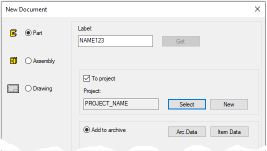
Create a new part
-
File > New > Part.
-
Enter the label.
-
Enter the archive information by clicking Arc.Data.
-
Select the project for the model.
-
Select OK.
-
Start sketching
-
New Sketch > To horizontal (XY) plane
-
Function: Polyline.
-
Draw a polyline
-
Click the origo as the first point (center of the blue cross), in the figure 1)
-
Move the cursor to the right (note the direction locks) and draw the lines clockwise.
-
When you draw the bottom horizontal line, find the location of the end point of the line at the origo.
-
-
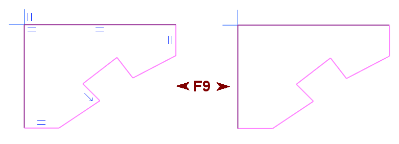
The program adds constraints when you draw lines: e.g. Coincident, parallel (with origin lines) and directions.. Constraints are shown in blue symbols.
-
You can show and hide the constraint symbols with the F9 function key.
-
When the cursor displays the X or Y symbol, click the cursor to lock the line in that direction. The line then gets a parallel constraint (= symbol)
-
When the cursor shows 45 °, the program locks the direction at an angle of 45 or -45 degrees and the line gets a direction constraint (arrow symbol).
Analyze the need to constraints
The color of the lines indicates the need for constraints
Depending on the degree of the constraints, the lines will have three colors (Black, Dark Purple or Light Purple)
-
Black. When a line and it's points are fully defined.
-
Dark purple. When the other end of a line or the center of a circle or arc has been defined .
-
Light purple. When a line position is not fixed, even though the line has some constraints like the length, angle, tangent, etc.
-
Red. When a line is overdefined.
-
Blue. When a line is copied from another part or earlier phase of a part.
-
Grey. When a line does not belong in this sketch.
Try to drag lines and points
-
The Vertex message line (lower left corner) should show: Ready (Press F1 for help).
-
If you have an action in progress press Esc key to end the it.
-
-
Select to a line or point and hold down the mouse selection button.
-
Move the cursor and release the selection button.
-
Cancel dragging, if necessary, with the Undo function or with Ctrl Z.
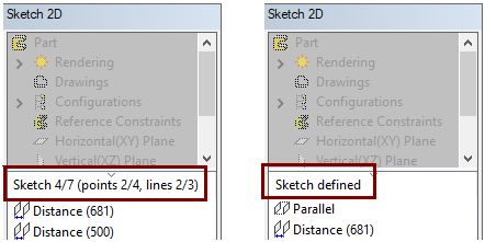
Vertex G4 does not require that the sketch should be fully defined. You can perform an operation (extrusion, etc.) at any stage once you are satisfied with a sketch.
But if the part is becoming parametric dimension-driven, then we recommend that the sketch is fully defined.
-
You can see the status of the sketch at the bottom of the feature tree.
-
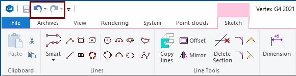
To undo the previous action, press the Undo
-
To redo the previous action, press the Redo

Note:
-
If you add several distance constraints at the same time, stop adding conditions and then select Undo, all these constraints you added will be deleted.
Dragging only works when you have no activity in progress (e.g. drawing a line or adding a condition).
-
Grab a line or point on the sketch and try to drag it from place to place.
-
If a line or point is dragged, then some condition may be missing.
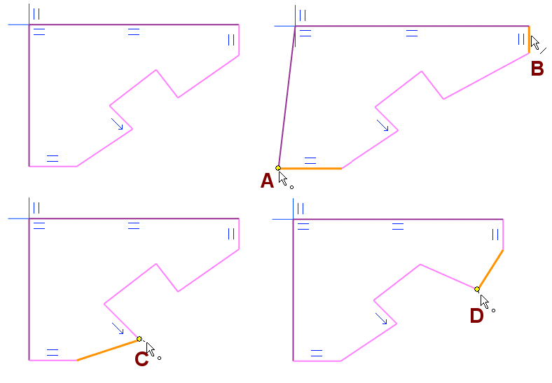
Lines and points are dragged using the degrees of freedom they have and at the same time they draw other related lines.
In the top figure points are grabbed in A,C,D, line is grabbed in B.
-
A = The vertical line did not have a parallel constraint, but the horizontal line has a parallel constraint.
-
B = The vertical line slides while maintaining its direction and length, because the line itself and the upper horizontal line have a parallel constraint.
-
C = A line with an arrow symbol has a direction constraint, so the direction of the line does not change even if its endpoint is dragged.
-
D = The position of the endpoints of the lines is not limited by any constraints, so the endpoints of both lines drag freely.
Add constraints
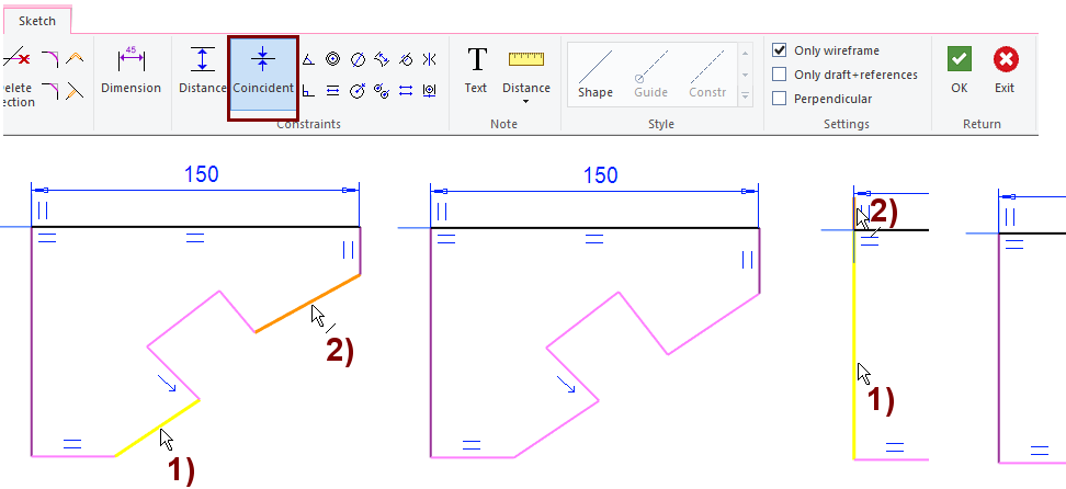
Add coinsident constraints
-
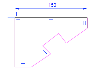
Function: Dimension.
-
Click the top horizontal line.
-
Enter the value: 150.
-
This dimension scales the other lines in the sketch.
-
-
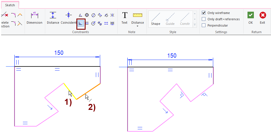
Function: Coinsident.
-
Click the first line, in the figure 1).
-
Click the second line, in the figure 2).
The coincident constraints given to lines means that the lines run on the same line passing through space, but they do not have to touch each other.
The coincident constraints given to points (the endpoints of the line, the centers of the circles and arcs) places those points on top of each other, that is, at the same point.
The coincident constraints given to line and point means that the point is on the same line passing through space, but the point does not have to touch the line.
An alternative coincident constraints method
-
Click the first line.
-
Press Ctrl key and click the second line.
-
Right-click function: Constraints > Coincident.
The coincident condition does not have its own (blue) symbol.
Add one perpendicular constraint
-
Function: Perpendicular.
-
Click the first line, in the figure 1).
-
Click the second line, in the figure 2).
If the other constraints do not limit the directions of the lines, then the first-indicated line retains its direction and the second-indicated line is directed perpendicular to it.
-
Click the first line.
-
Press Ctrl key and click the second line.
-
Right-click function: Constraints > Perpendicular.
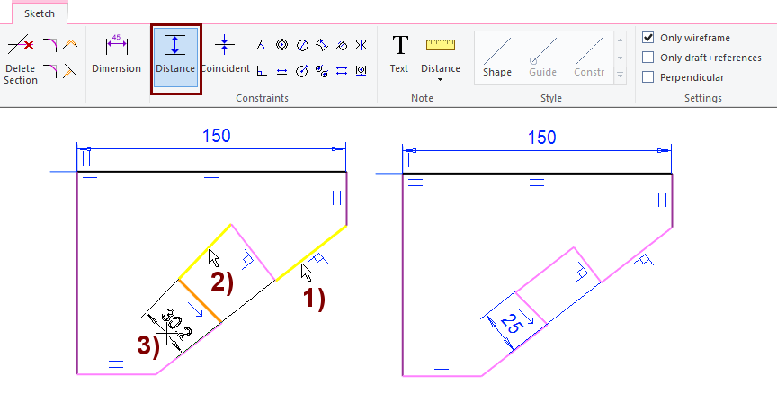
Enter the depth of the hollow using the distance constraint.
-
Function: Distance.
-
Click the first line, in the figure 1).
-
Click the second line, in the figure 2).
-
Select the location of the dimension, in the figure 3).
-
Enter the correct value: 25.
If the other constraints do not limit the directions of the lines, then the first-indicated line retains its direction and the second-indicated line is directed parallel to it.
-
Click the first line.
-
Press Ctrl key and click the second line.
-
Right-click function: Constraints > Distance.
-
Select the location of the dimension.
-
Enter the correct value.
When the constraint is between two segments:
-
If you use a Dimension constraint between two parallel lines, then it works like a Distance constraint.
-
If you use a Dimension constraint between two lines in different directions, then it works like a Angle constraint.
-
If you use the Distance constraint between two lines in different directions, it will orient the lines parallel.
The Dimension constraint is more general than Distance constraint.
-
If you click to one line segment, the program draws a dimension for it and assumes that you select the dimension a location and the correct value.
-
In addition, if you click to another line segment, the program suggests either a distance or an angle.
-
If you click to an arc or ellipse, the program suggests a radius.
-
If you click to a circle, the program suggests a diameter.
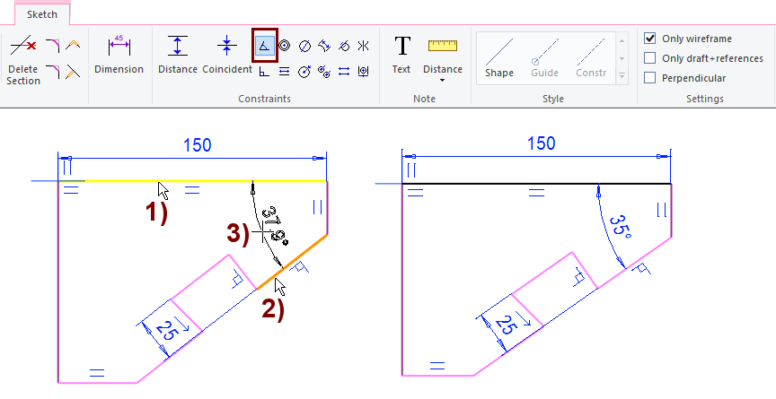
Add one angle constraint
-
Function: Angle.
-
Click the first line, in the figure 1).
-
Click the second line, in the figure 2).
-
Select the location of the dimension, in the figure 3).
-
Enter the correct value: 35.
If the other constraints do not limit the directions of the lines, then the first-indicated line retains its direction and the second-indicated line is directed at an angle with it.
-
Click the first line.
-
Press Ctrl key and click the second line.
-
Right-click function: Constraints > Angle.
-
Select the location of the dimension.
-
Enter the correct value.
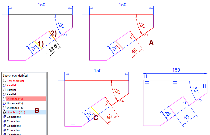
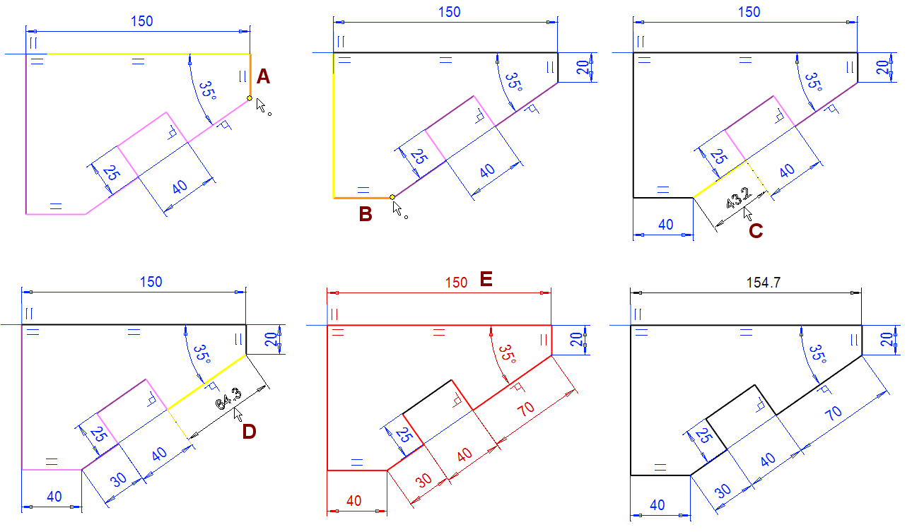
Add distance condition to hollow - Sketch will become over defined
The aim is to give a hollow width of 40 mm using the distance constraint. But in the geometry shown in the figure, both lines are already subject to a constraint that determines the direction.
-
There is a direction constraint on line 1) in the figure (there is an arrow next to the line and the Direction (315) can be found under the feature tree.
-
Line 2) in the figure has a perpendicularity constraint to a line that has an angular constraint with the line which has parallel constraint.
-
Therefore, the constraint cannot be fulfilled even if the constraint is added. Figure A.
-
This is displayed above the list of constraints as Sketch over defined and so that conflicting constraints are colored red in both the draft and the list of constraints.
It is not advisable to continue sketching until the Over defined situation has been removed.
-
Use the Undo function to delete the last added constraint (
-
Or remove any other constraint that conflicts with this constraint.
In the case of the figure, the direction constraint was accidentally created during the sketch lines, so you should delete it:
-
Press Esc to stop entering constraint, if the function is still running.
-
Select a constraint (from a list of constraint, Figure B or geometry, Figure C.)
-
Right-click function: Delete or press Delete key.
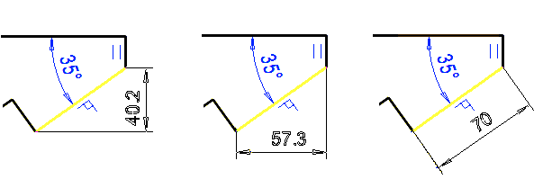
Add the remaining dimension constraints
-
A: The distance 20 is given between the line and the point. (As an alternative to the Dimension constraint for the vertical line).
-
B: The distance 20 is given between the line and the point. (As an alternative to the Dimension constraint for the horisontal line).
-
C: Dimension 30 is given for the line.
-
D: Dimension 70 is given for the line.
-
As a result, the sketch is over defined.
-
-
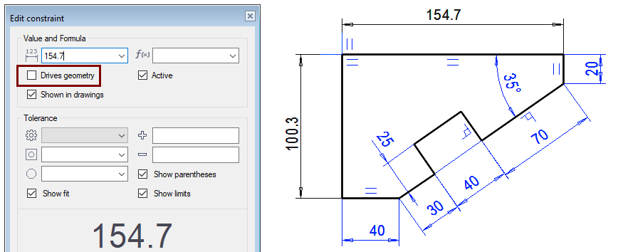
E: Edit the dimension (150)
-
Double-click a dimension or select a dimension and right-click funtion Properties.
-
Remove selection Drives geometry.
-
When dimensioning an oblique line, it depends on the position of the cursor, which direction the dimension will be oriented:
-
Vertically.
-
Horizontally.
-
In the direction of the line.
Move the cursor to the size you want, and then click the cursor.
Non drives geometry
You can add Dimension, Distance, or Angle constraint to the sketch and remove the property Drives geometry from them.
-
When geometry is modified, such dimensions change with it, but they do not control the geometry.
-
Such dimensions can help you sketch out the dimensions that result from the constraints.
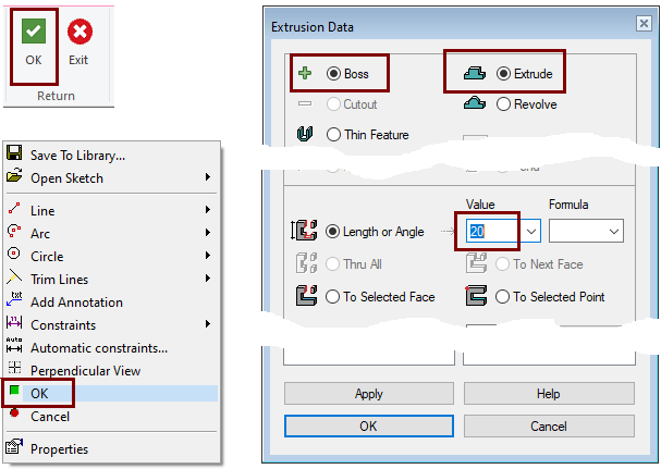
Perform the boss extrusion operation
-
Stop sketching (the green OK button).
-
Select: Boss and Extrude.
-
Select Length or Angle and enter the thickness of the part: 20.
-
Click OK.
Rotate the part and select a surface for sketching
-
Click and hold the middle mouse button while moving the mouse slowly.
-
Rotate the model to the position shown on the right and release the mouse button.
-
Select Face.

The Tool Strip has seven buttons that allow you to flip the model in specific directions.
-
Starting from left: Front, top, left, right, isometric, select from model that is rotated perpendicularly and to the right is a list of projections where you can save your own directions.
The middle button of the mouse while holding down the button causes the model to rotate with respect to the horizontal or vertical axis, depending on the movement of the cursor.
Shift + Left Mouse Button => does the same thing as above.
Shift + Right mouse button => Zoom the model flexibly (More flexible than the mouse wheel, which allows movement to be jerky).
Shift + Middle mouse button => Pan i.e. move vertically and vertically without twists.
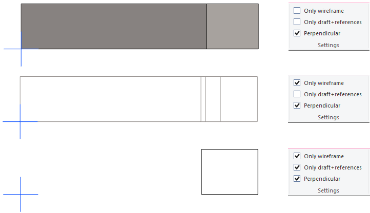
Proceed with sketching
-
Select the face.
-
Right-click function: New Sketch > Face.
The part is drawn in either rendered or iron wire.
-
In the wireframe drawing all lines in the part are visible. This is useful if there are shapes on the other side of the part to which you want to draw sketch lines. This can also be a disadvantage if the sketch shows unnecessary lines.
-
Only draft and references shows the paragraph lines only those that belong to the sketch plane border lines.
-
When the Perpendicular option is selected, the sketch is always rotated perpendicular when the part is selected to be skeched.
-
During skeching you can rotate the model to the desired position.
-
If you want to rotate the draft perpendicular again, use the Perpendicular function in the right click menu.
-
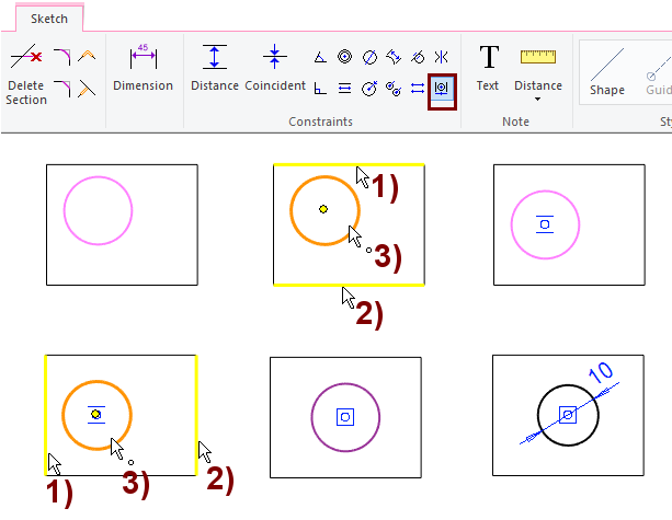
Draw a circle and center it
Draw a circle
-
Function: Circle with center and radii point

-
Select to the location of the center point.
-
Select to a point on the perimeter.
Enter the centering constraint
-
Function: Add Centering Constraint.
-
Click the first line, figure 1).
-
Click the second line, figure 2).
-
Click the center point of the circle, figure 3).
Enter the diameter of circle: 10.
-
Click the first line.
-
Press Ctrl key and click the second line.
-
Right-click function: Constraints. > Midpoint.
-
Click the center point of the circle.
Perform the cutout extrusion operation
-
Stop sketching (the green OK button).
-
Select: Cutout and Extrude.
-
Select: Thru All.
-
Click OK.
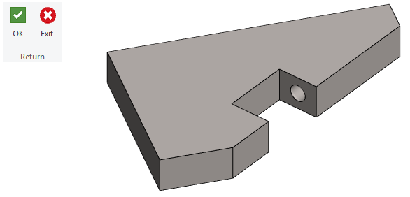
Edit the extrusion
The purpose is to extrude a hole through the entire part, so move the cursor to the Extrusion in the feature tree and select the right click function: Edit operation.
-
Select an option: In both directions.

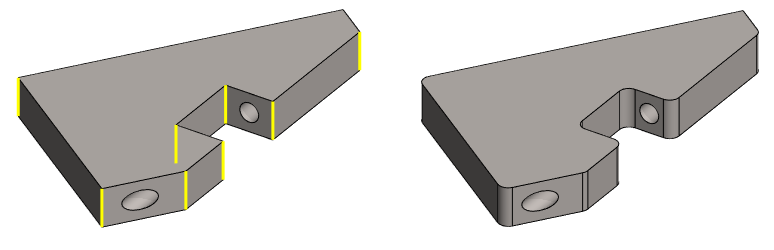
Make the necessary roundings in the part modeling state.
-
Click all the lines you want to round at once (Keep Ctrl key down).
-
Right-click function: Add Round/Bevel > Single Edge Round.
-
Enter Radius: 5.
-
OK.
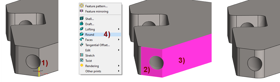
The hole prevents rounding of one edge
The edge 1) shown in the figure cannot be rounded if a line is selected, figure 1).
-
Click the first face, figure 2).
-
Press Ctrl key and click the second face, figure 3).
-
Right-click function: Round, figure 4).
-
Enter Radius: 5.
-
OK.
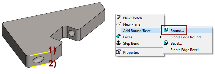
Create rounding chains for the top and bottom edges
-
Click one line at the top edge.
-
Press Ctrl key and click second line at the bottom edge.
-
Right-click function: Add Round/Bevel > Round.
-
Enter Radius: 1.
-
OK.
-
Singe Edge Round rounds only one segment.
-
Round searches the chain tangential to the indicated line and rounds the entire line chain.
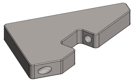
Save the model
-
File > Save or click


Further processing of the model (covered in other exercises)
You can add a material item to the model with the right-click function Item Data.
-
Material data is shown in the parts list of drawing.
You can create a drawing for the model:
-
In the feature tree, select Drawings.
-
Right-click function: New Drawing.