
These instructions apply to Vertex G4Plant version 2024 (30.0.0) and later.
General
Until version 2023, adding your own primary supports to the standard supports in Vertex G4Plant was, in practice, technically impossible. Vertex G4Plant 2024 introduces a library technology that allows you to create and save your own custom primary supports in a library.

You can now build your support library using dimension-driven part models, which are then used to create the actual assemblies. The item data of the supports is stored in a library-specific database that provides versatile options for controlling support behavior when supports are added to a pipeline. The instructions below describe how the standard Vertex library has been created. You can use the models we have created as templates for your own supports or start from scratch.
In any case, we recommend that you familiarize yourself with the support models provided by Vertex before you begin modeling your own supports. Models for all support types can be found in the standard section of the component library under Plant > Primarysupports and its subfolders.
Modeling a clamp and requirements
We modeled the clamp using feature-based modeling tools. Formulas and dimension tables were used to create dimension-driven models. Standard dimensions and variables were utilized when parameterizing the clamp model. As an example, see the model PSK7307 in the standard section of the component library under Plant > Primarysupports > Clamps.
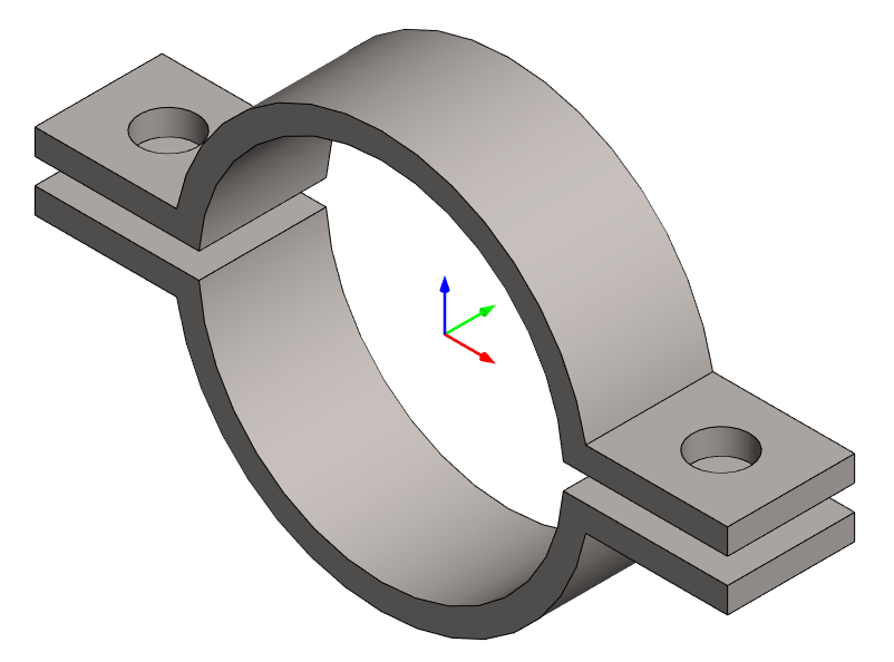
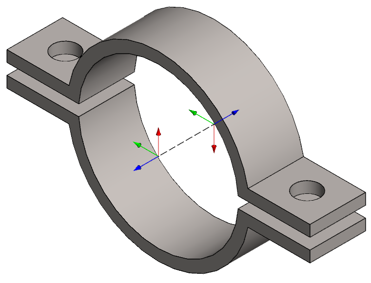
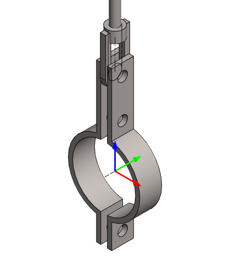
The origin of the clamp model must be located at the center point of the model, as illustrated in the image on the right.
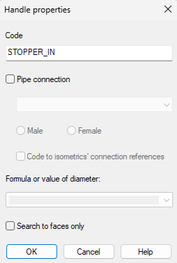
The clamp requires a guide curve along its centerline from edge to edge. We added handles (insertion points) to both ends of this centerline using the Edit named elements function. These handles enable the automatic attachment of stoppers to the clamp. The handle identifiers must be STOPPER_IN and STOPPER_OUT. See the image below for details on how the other handle properties must be defined. The blue arrows of the handles must point along the centerline, that is, in the direction of the Y-axis (see the lower clamp image on the right).
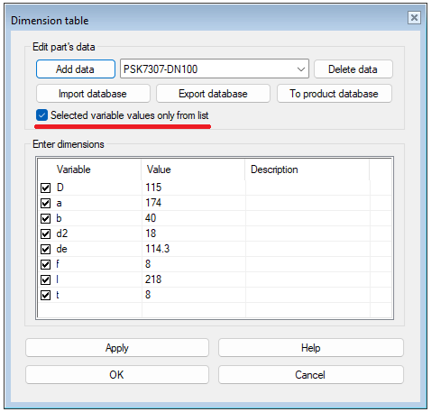
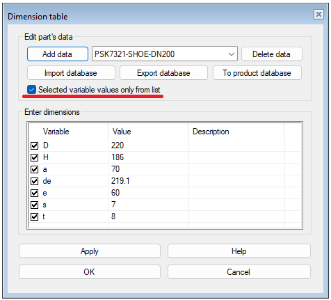
The identifier of each dimension variant stored in the dimension table is also important. Using the variables defined in these identifiers, the software can correctly vary the created supports for pipes with different outside diameters. The checkbox Selected variable values only from list must be enabled in the dimension table.
The identifier of a clamp variant must end with the nominal pipe size, separated from the rest of the identifier by a hyphen:
-
Clamp A: ...PSK7307-DN100, PSK7307-DN125, PSK7307-DN150...
NOTE! Before saving the clamp to the library, ensure that it has not been converted into a pipe component (parts’s Properties). This can happen if the handles are added in the same way as they are typically added to pipe components. If the clamp is saved to the library as a pipe component, it will not vary correctly in assemblies.
Modeling a slide support and requirements
1. Slide shoes
We modeled the slide shoe using feature-based modeling tools. Formulas and dimension tables were used to create dimension-driven models. Standard dimensions and variables were utilized when parameterizing the slide shoe model. As an example, see the model PSK7321-SHOE in the standard section of the component library under Plant > Primarysupports > Slides.
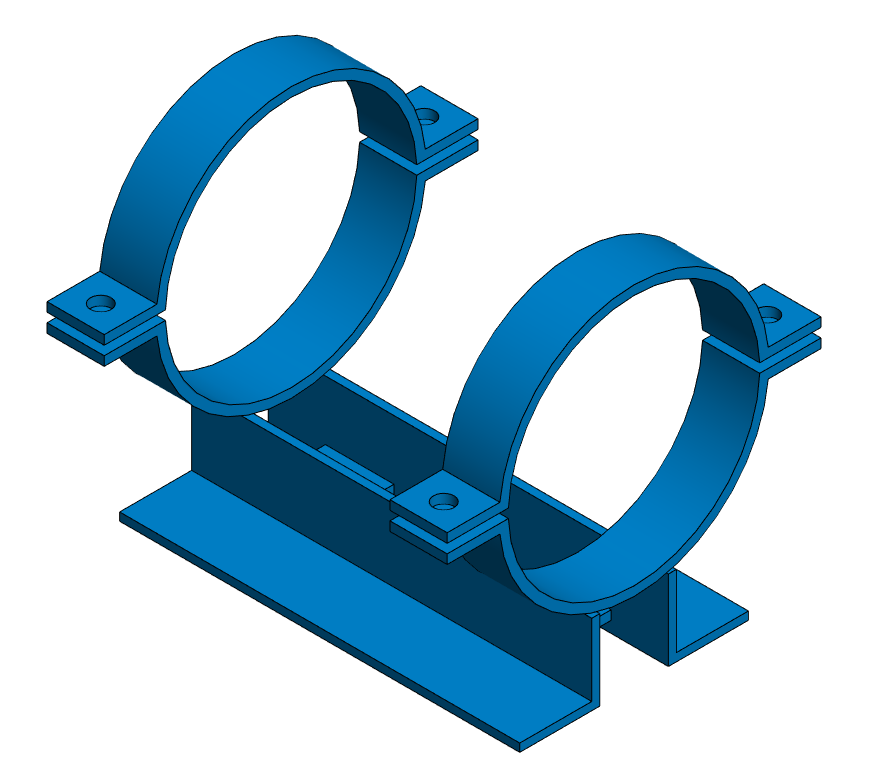
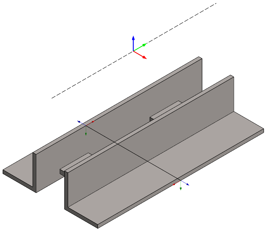
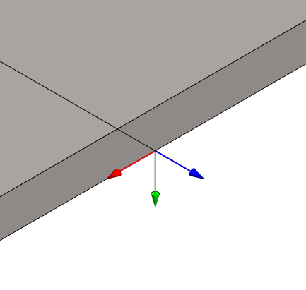
The origin of the slide shoe model must be located on the centerline of the supported pipe and centered longitudinally along the support (in the Y-axis direction). This is illustrated in the image on the right. We created a guide curve for the slide shoe at the centerline of the supported pipe (in the Y-axis direction), extending from edge to edge.
We also created a second guide curve. This curve must run in the X-axis direction (red arrow). It must be positioned at the bottom of the support so that its endpoints are located at the midpoints of the bottom edge. We added handles (insertion points) to the ends of this line, enabling the automatic attachment of lugs and guides to the slide shoe. The handle identifiers must be LUG1 and LUG2. See the image below for details on how the other handle properties must be defined. The green arrows of the handles must point downward, that is, in the negative Z-axis direction (see the image on the right).
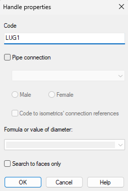
The identifier of each dimension variant stored in the dimension table is also important. Using the variables defined in these identifiers, the software can correctly vary the created supports for pipes with different outside diameters. The checkbox Selected variable values only from list must be enabled in the dimension table.
The identifier of a slide shoe variant must end with the nominal pipe size, separated from the rest of the identifier by a hyphen:
-
Slide shoe PSK7321: ...PSK7321-SHOE-DN150, PSK7321-SHOE-DN200, PSK7321-SHOE-DN250...
2. Slide supports
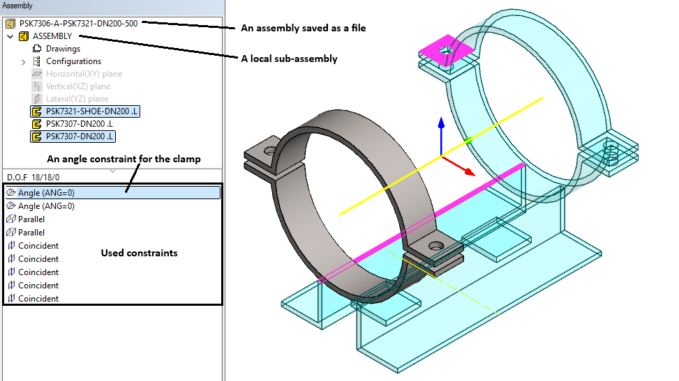
A slide support is an assembly that we created from a slide shoe and clamps using assembly constraints. As an example, see the model PSK7306-A-PSK7321-DN200-500 in the standard section of the component library under Plant > Primarysupports > Slides.
First, we created a new assembly. It is recommended that the assembly be saved as a file in an appropriate location. Next, we added a new local sub-assembly. This sub-assembly can be named freely (for example, ASSEMBLY).
We added the slide shoe to the sub-assembly from the component library. Custom parts created by the user can be found in the component library under (shared). We positioned the slide shoe so that its origin coincided with the assembly origin and the assumed pipe routing direction followed the Y-axis. The slide shoe was fixed in place using assembly constraints. The default assembly planes were used when creating the constraints.
Next, we added the required number of clamps to the assembly from the component library. They were positioned in the assembly using constraints. The STOPPER_OUT handle must point away from the support origin. To allow the clamps to be rotated to different installation angles, we added an angular constraint to the assembly with the formula ANG.
Note! Lugs and stoppers must not be added to the assembly. Adding them to the assembly is handled automatically through the database.
Modeling a hanger support and requirements
1. Part models
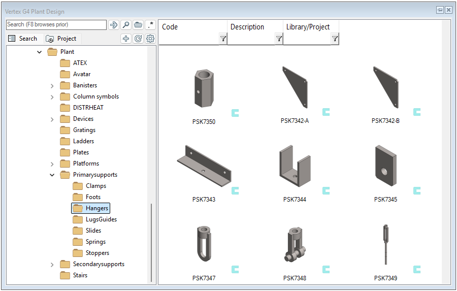
We modeled the hanger support components using feature-based modeling tools. Formulas and dimension tables were used to create dimension-driven models. Standard dimensions and variables were utilized when parameterizing the models. As examples, see the models PSK7342-A...PSK7350 in the standard section of the component library under Plant > Primarysupports > Hangers.
Particular attention must be paid to the hanger support components whose dimensions vary on a case-by-case basis. In practice, these are the hanger rod (PSK7341) and the cross beams (PSK7346-A and PSK7346-B). These components cannot be added to an assembly directly from the component library. Instead, they must be modeled as local parts within the assembly. An example can be found by opening the model PSK7340-YK1-AR4-PSK7321-200-500 from the component library under Plant > Primarysupports > Hangers.
There is no mandatory location for the origin of a hanger support component. However, we recommend that the component geometry be referenced to the part model origin. Clamps must be modeled as described in the earlier instructions.
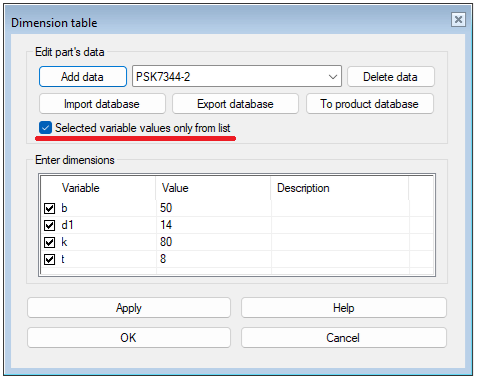
The identifier of each dimension variant stored in the dimension table is also important. Using the variables defined in these identifiers, the software can correctly vary the supports for pipes with different outside diameters. The checkbox Selected variable values only from list must be enabled in the dimension table.
The identifiers of hanger support components must end with the load class, separated from the rest of the identifier by a hyphen:
-
Attachment B: PSK7344-1, PSK7344-2, PSK7344-3...
-
Eye nut: PSK7347-1, PSK7347-2, PSK7347-3...
2. Hanger supports
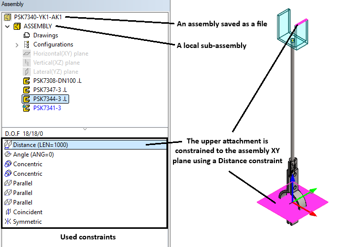
A hanger support is an assembly built using components according to the selected upper and lower attachment types. The components are connected using assembly constraints. As examples, see the models PSK7340-YK1-AK1 and PSK7340-YK1-AR4-PSK7321-200-500 in the standard section of the component library under Plant > Primarysupports > Hangers.
First, we created a new assembly. It is recommended that the assembly be saved as a file in an appropriate location. Next, we added a new local sub-assembly. This sub-assembly can be named freely (for example, ASSEMBLY).
The first components added to the sub-assembly from the component library were the clamp or clamps. Custom parts created by the user can be found in the component library under (shared). In assemblies containing two clamps, additional components may be required when creating the assembly constraints, so these should be added at the beginning if necessary.
-
In assemblies with a single clamp, we positioned the clamp origin at the assembly origin so that the clamp centerline follows the assumed pipe routing direction (Y-axis). The clamp was fixed in place using assembly constraints. The default assembly planes were used when creating the constraints.
-
In assemblies with two clamps, the clamps were positioned around the origin according to the design requirements.
After the clamps had been added, the remaining hanger support components were inserted from the component library. Assembly constraints were used to position the components. The hanger support was assembled from the bottom upward, that is, in the positive Z-axis direction (example: PSK7340-YK1-AK1).
Note! A hanger support intended for a vertical pipe must be built so that the pipe routing direction in the assembly is along the Y-axis. This means that the other support components must also be oriented along the Y-axis (example: PSK7340-YK1-AK2). This allows the software to place the support correctly on a vertical pipe.
Each hanger support contains either one or two hanger rods. This component must be modeled locally within the assembly. Using a dimension table, we defined all variables except the length. In the support models provided by Vertex, the hanger rod is constrained to both the lower and upper attachments. The rod automatically "stretches" to the required length as the upper attachment moves. The upper attachment is constrained to the assembly XY plane using a Distance constraint with the formula LEN. The installation length (dimension L in PSK standards) is ultimately defined when the support is inserted. If the support contains two hanger rods, the formulas are LEN1 and LEN2.
The upper attachment may need to be rotated depending on the installation situation. We added an Angle constraint to the upper attachment and assigned it the formula ANG. If two upper attachments are used, the formulas are ANG1 and ANG2.
The cross beam must also be modeled locally within the support assembly because its length varies according to the beam hole spacing (example: PSK7340-YK1-AR4-PSK7321-200-500). For heavy-duty beams, the profile used may also vary depending on the application.
Modeling a foot support and requirements
Foot support A consists of a clamp, a U-beam, and an attachment plate (except structure A3).
Foot support B consists of a clamp, a tube spar, and an attachment plate (except structure B3).
Foot support C consists of a pipe and an attachment plate (except structure C3).
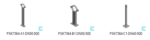
Of the components listed above, only the clamp comes from the component library. The other components are modeled locally. As examples, refer to the models available in the standard section of the component library under Plant > Primarysupports > Foots (for example, PSK7364-A1-DN50-500 and PSK7364-C1-DN40-500).
Structure A and B
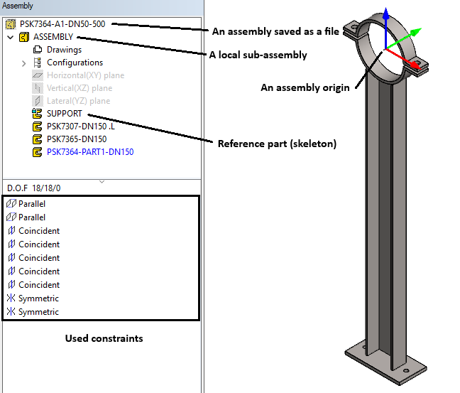
First, we created a new assembly. It is recommended to save it as a file in an appropriate location. We then added a new local sub-assembly to it. This sub-assembly can be named freely (for example, ASSEMBLY).
A local part named SUPPORT was created in the local sub-assembly. In this model, we created a reference plane whose offset in the negative Z-axis direction from the assembly origin is defined by the formula LEN.
The first component added to the sub-assembly from the component library was the clamp. You can find the parts you create in the shared component library. We positioned the clamp by aligning its origin with the assembly origin so that the centerline of the clamp is in the direction of the assumed pipe run (Y-axis). The clamp was fixed in place using assembly constraints. The default assembly planes were utilized in the constraints.
We modeled the attachment plate as a local part on the previously defined reference plane. Variables for the attachment plate were defined using a dimension table. The last characters of the attachment plate identifier must correspond to the nominal size of the associated pipe, for example PSK7365-DN150. This allows the software to select the correct attachment plate variation. The plate was fixed in place using constraints.
Finally, we modeled the beam as a local part. Variables for the beam were defined using a dimension table. The last characters of the beam identifier must correspond to the nominal size of the associated pipe, for example PSK7364-PART1-DN150. This allows the software to select the correct beam variation. The beam was fixed in place using constraints so that it follows either the attachment plate (structures A1, A2, B1, and B2) or directly the reference plane (structures A3 and B3). The installation length (dimension L in the PSK standards) is ultimately defined when the support is inserted, based on which the beam "stretches" to its required length.
Structure C
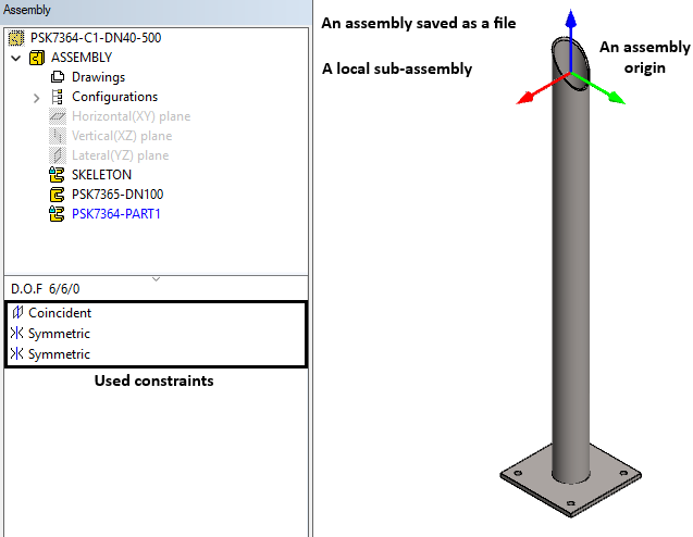
First, we created a new assembly. It is recommended to save it as a file in an appropriate location. We then added a new local sub-assembly to it. This sub-assembly can be named freely (for example, ASSEMBLY).
A local part named SKELETON was created in the local sub-assembly. In this model, we created a reference plane whose offset in the negative Z-axis direction from the assembly origin is defined by the formula LEN.
First, we modeled the attachment plate as a local part on the previously defined reference plane. Variables for the attachment plate were defined using a dimension table. The last characters of the attachment plate identifier must correspond to the nominal size of the associated pipe, for example PSK7365-DN150. This allows the software to select the correct attachment plate variation. The plate was fixed in place using constraints.
Finally, we modeled the pipe as a local part. The curved surface at the end of the pipe must be oriented so that the Y-axis (green arrow) points away from the "cup", as shown in the image below.
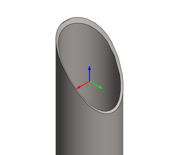
Variables for the pipe were defined using a dimension table. The last characters of the pipe identifier must correspond to the nominal size of the associated pipe, for example PSK7364-PART1-DN150. This allows the software to select the correct beam variation. The beam was fixed in place using constraints so that it follows either the attachment plate (structures C1 and C2) or directly the reference plane (structure C3). The installation length (dimension L in the PSK standards) is ultimately defined when the support is inserted, based on which the beam "stretches" to its required length.
Modeling of Stoppers and Guides Requirements
1. Stoppers
We modeled the stoppers using feature-based modeling tools. Formulas and dimension tables were used to create scalable models. Dimensions and variables from the applicable standards were utilized when parameterizing the models. As an example, refer to model PSK7362-A1 located in the component library under Plant > Primarysupports > Stoppers.
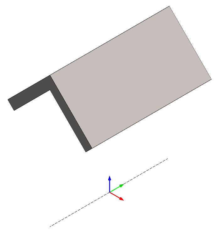
The origin of the stopper model shall be located on the centerline of the supported pipe and centered along the length of the stopper (Y-axis direction). This is illustrated in the image on the right. We drew a reference line (guide curve) for the stopper along the centerline of the supported pipe (Y-axis direction), extending from one edge of the stopper to the other.
A handle (insertion point) was added to one end of the centerline using the Edit named elements function. This handle enables the stopper to be automatically connected to the clamp. The handle identifier must be STOPPER. See the image below for the required handle properties. The blue arrow of the handle must point parallel to the centerline, i.e., in the Y-axis direction.
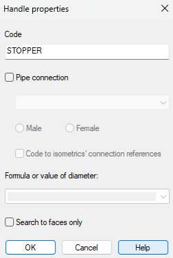
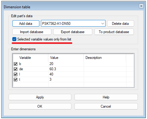
The identifiers of the size variants stored in the dimension table are also important. Based on the variables defined in these identifiers, the software can correctly vary the created stoppers for pipes with different outside diameters. The Selected variable values only from list checkbox must be enabled in the dimension table.
The stopper identifier must end with the nominal pipe size, separated by a hyphen:
-
Stopper A1: PSK7362-A1-DN50, PSK7362-A1-DN65, PSK7362-A1-DN80...
NOTE! Before saving the model to the library, ensure that the stopper has not been converted into a pipe component (part’s Properties). This may occur if the handle is added in the same way as for pipe components. The stopper will not vary correctly in assemblies if it is saved to the library as a pipe component.
2. Lugs
We modeled the lugs using feature-based modeling tools. Dimensions and variables from the applicable standards were utilized. As examples, refer to models PSK7360-A and PSK7360-B located in the component library under Plant > Primarysupport > LugsGuides.
There is no absolute requirement for the location of the model origin for a lug. In the components created by Vertex, the origin is located at the center of the part in the Y-direction and at the "left edge" of the part in the X-direction. An example is shown in the image on the right.
A centerline was added to the models to assist with positioning the handle (insertion point). The handle was added using the Edit named elements function. This handle enables the lug to be automatically connected to the slide shoe. The handle identifier must be LUG. See the image below for the required handle properties. The blue arrow of the handle must point parallel to the centerline.
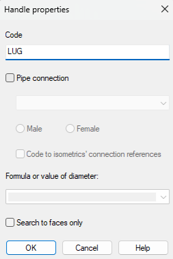
The identifiers of the size variants stored in the dimension table are also important. Based on the variables defined in these identifiers, the software can correctly vary the created lugs for pipes with different outside diameters. The Selected variable values only from list checkbox must be enabled in the dimension table.
The lug identifier must end with the nominal pipe size, separated by a hyphen:
-
Lug A: PSK7360-A-DN50, PSK7360-A-DN65, PSK7360-A-DN80...
NOTE! Before saving the model to the library, ensure that the lug has not been converted into a pipe component (parts's Properties). This may occur if the handle is added in the same way as for pipe components. The lug will not be positioned correctly in assemblies if it is saved to the library as a pipe component.
3. Guides
We modeled the guides using feature-based modeling tools. Dimensions and variables from the applicable standards were utilized. As examples, refer to models PSK7361-A and PSK7361-B located in the component library under Plant > Primarysupports > LugsGuides.
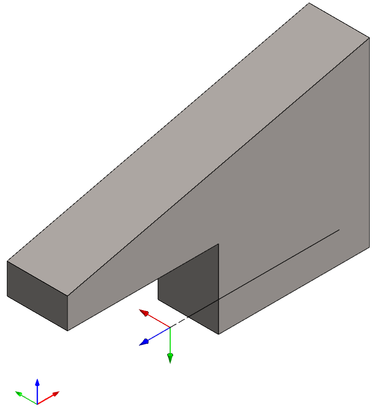
There is no absolute requirement for the location of the model origin for a guide. In the components created by Vertex, the origin is located at the center of the part in the Y-direction and at the "left edge" of the part in the X-direction. An example is shown in the image on the right.
A centerline was added to the models to assist with positioning the handle (insertion point). The handle was added using the Edit named elements function. This handle enables the guide to be automatically connected to the slide shoe. The handle identifier must be LUG. See the image below for the required handle properties. The blue arrow of the handle must point parallel to the centerline.
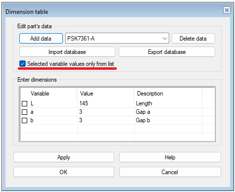
The size variant identifier stored in the dimension table is the same as the model identifier. The Selected variable values only from list checkbox must be enabled in the dimension table. The guide length and clearances are freely definable values when the guides are positioned in completed support assemblies on piping systems.
NOTE! Before saving the model to the library, ensure that the guide has not been converted into a pipe component (parts's Properties). This may occur if the handle is added in the same way as for pipe components. The guide will not be positioned correctly in assemblies if it is saved to the library as a pipe component.
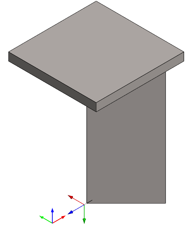
How to build own primary support library
With the new library technology, users can finally create their own supports for the program libraries. Earlier, we explained how the standard library was created, how support models were modelled, and how the data was entered. In this section, we describe in greater depth and detail the steps that allow you to build your own library.
Overview of primary support libraries
We briefly introduce the functions and key files related to the new library technology.
Libraries function
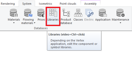
You can manage the activity of primary support libraries and examine the basic data of primary supports in the standard libraries through the Libraries function. By default, the PSK library is available, based on new, modelled supports. You can also activate the old library, PSK_OLD, which uses parameter-based programs. In the tree of the Libraries browser, find the correct library and select it by clicking the left mouse button. Then right-click to open the context menu, where you can Activate or Deactivate the selected library. Your own library requires creating a new library; we will return to this when the instructions cover saving your own support.
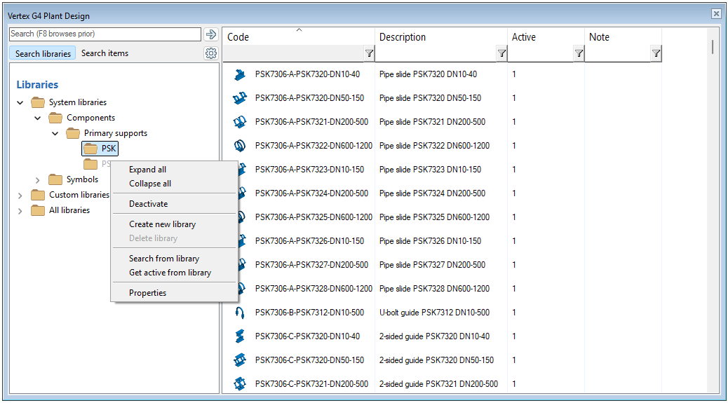
The actual primary support parts and assemblies are displayed in the browser on the right. You can inspect the data of supports in the standard library by double-clicking the support row with the left mouse button. NOTE! You cannot edit the data of a support in the standard library; you can only view it. You can edit your own primary supports through the Libraries function. First, you must create your own library and add content to it.
The image below shows the first-page data for the slide support assembly PSK7306-A-PSK7320DN50-150. Next, we will go through the pages one by one and explain what information can and must be entered for a support.
Page 1
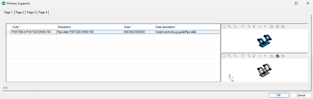
Code is the unique identifier for a support. Standard-library identifiers describe the type of assembly through standards, type codes, and size range. The identifier can be chosen freely. This information is mandatory.
Description describes the support. For some supports in the standard library, the description is formed from combinations of keywords and text in complib_prompts.xml (see Contents of the complibs folder below). NOTE! This function is currently available automatically only for standard libraries. The example support description is written in the standard-library database as {SLIDE + " PSK7320 DN50-150"}, where SLIDE is the keyword and the text between the quotation marks is the text. The braces { } are required so that the program can change the keyword SLIDE to Slide support when the description is displayed in different functions. Keywords can also be used to create a language translation. If you are interested in using keywords when creating your own library, contact our customer service for further guidance.
Class defines what kind of support is involved. There may be one or more values. If there are several, separate them with a vertical bar |. A value can be entered manually or selected from the drop-down menu. Typical classifications are ANCH = anchor point, DUCK = foot support, GUID = guided slide support, HANG = hanger support, SKID = slide support, and SPRG = spring support. This information is mandatory.
Class description is descriptive text for the classification. In the standard library, the classification description is written using keywords. NOTE! This function is currently available automatically only for standard libraries. The classification description for the example support is written in the standard-library database as {ANCHOR_A + "|" + GUIDE_A + "|" + SLIDE}.
Page 2
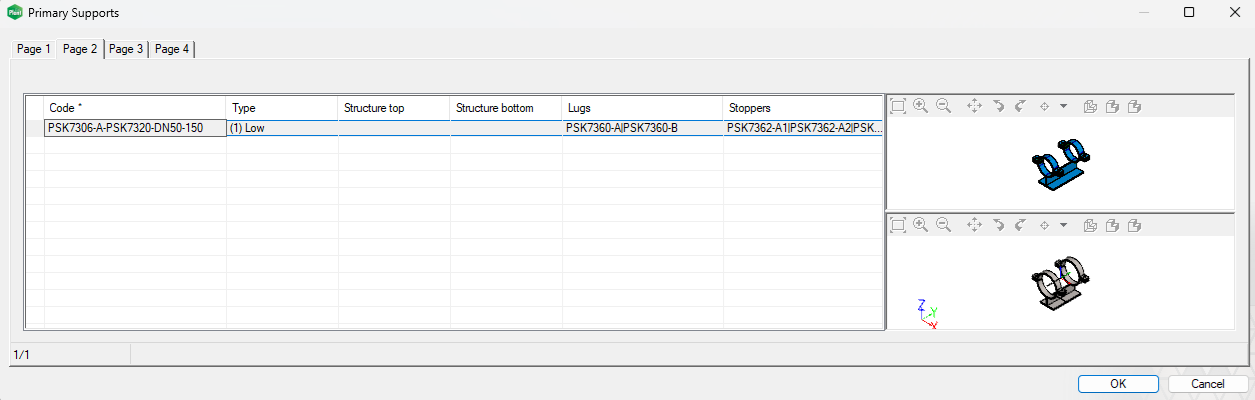
Type is used for slide supports to indicate whether the support is low, high, or extra high. For plastic pipe supports, it indicates whether the pipe is dimensioned by its internal or external diameter. This information is not normally used for hanger and foot supports. The information is shown when selecting a primary support.
Structure top is used for hanger and spring supports to indicate the attachment method at the top end of the structure. The standard library uses the structures YK1–6 specified in the PSK standards.
Structure bottom is used for hanger and spring supports to indicate the support method at the bottom end of the structure. The standard library uses the light structures AK1–6 and heavy structures AR1–6 specified in the PSK standards.
The Lugs field specifies the identifiers of the lugs or guides that can be selected when adding a slide support. If the field is empty, guides cannot be added. The standard library contains lugs PSK 7360-A and PSK 7360-B, and guides PSK 7361-A and PSK 7361-B.
The Stoppers field specifies the identifiers of the stoppers that can be selected when adding a support. If the field is empty, stoppers cannot be added. The standard library contains stoppers PSK7362-A1/2/3, PSK7362-B1/2/3, and PSK7362-C1/2/3.
Page 3
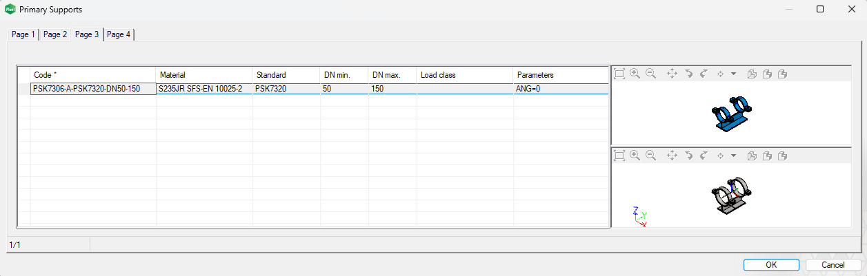
Material is the material of the support when it can be determined unmistakably. You can use the drop-down menu in the field to select a value. The field may be left empty, in which case the material can be freely defined when adding the support.
Standard defines the support standard. In the standard library, this field contains the standard specified by the PSK standard.
The DN min. field specifies the smallest nominal pipe size (DN) for which the support varies. The variation is determined by the clamp model used in the assembly.
The DN max. field specifies the largest nominal pipe size (DN) for which the support varies. The variation is determined by the clamp model used in the assembly.
Load class is a value used for hanger supports to indicate the load class of the support. In the standard library, the load-class values follow the PSK standards. For some structures, the nominal pipe size defines the load class; for others, it can be selected.
The Parameters field can contain default dimensional conditions for primary support assemblies that have a formula value. The Parameters field can set a default value for a dimensional variable; for example, the clamp installation angle of a slide support is zero by default (ANG=0). If a dimensional variable must be defined when the support is added, enter the variable with the value ? in the Parameters field (for example, LEN=?). In the standard library, foot supports have a maximum length parameter (for example, MAX_LEN=300), which prevents excessively long foot supports from being added.
Page 4
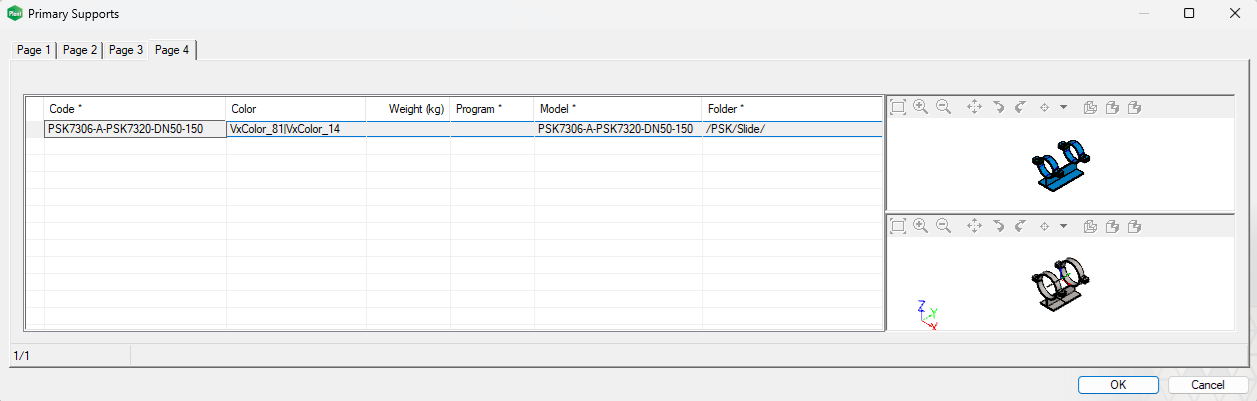
Color is the color assigned to the entire primary support when it is added to a pipeline. The color can easily be selected from the drop-down menu. Several colors can be specified. They are assigned according to the support classifications. Separate colors with a vertical bar |. In the example, classification ANCH receives color VxColor_81. Classifications GUID and SKID receive color VxColor_41. The program reads the vertical bars and interprets the last two classifications as using the same color when they are not separated by another vertical bar.
Weight (kg) – If there is only one fixed-dimension variation, its weight can be entered in this field. Normally, the field is left empty and the program calculates the weight according to the situation.
The Program field applies only to the old parameter-program-based library PSK_OLD. For model-based supports, the field is always empty.
The Model field contains the model name under which it was saved in the component library. This information is mandatory for model-based supports. For supports in the PSK_OLD library, this field is always empty.
The Folder field specifies the folder in which the support is found when using Add primary support. The folder structure can be freely defined and does not need to follow the same structure as the models. This information is mandatory.
Contents of the complibs folder
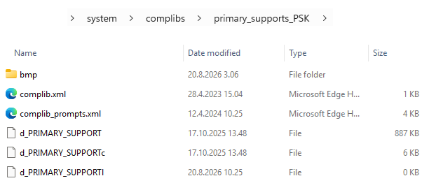
Files related to the basic data of the standard libraries are located in \system\complibs\primary_supports_PSK and \system\complibs\primary_supports_PSK_OLD.
The bmp folder contains preview images of primary supports, displayed when using Add primary support and Libraries. The preview images are generally PNG files. The image filename is usually the same as the identifier of the primary support part or assembly.
The complib.xml file contains the library's basic data, such as its description and activity status. For your own library, this data is edited through Libraries.
The complib_prompts.xml file contains a list of keywords used to manage, for example, the formation of descriptions and language versions. NOTE! This file is used only with standard libraries. It is not created automatically when creating your own library. If you are interested in this option, contact our customer service for further guidance.
The d_PRIMARY_SUPPORT database contains the basic data of primary supports. For your own primary supports, this data is defined when saving them to the library. For your own library, the data is edited through Libraries.
Contents of the components folder
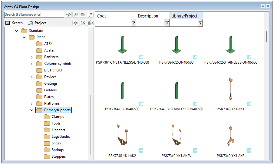
The models of support assemblies and parts are located in the component library under Standard > Plant > Primarysupports and its subfolders. In File Explorer, the models are located at \system\components\Plant\Primarysupports and its subfolders.
The modelling details of the models have already been explained in earlier sections of this instruction.
As a user, you can now save support models you have created to the library. A support model must be a pipe part or assembly without pipe clamps. Save the model to the component library folder \shared\components\Plant\Primarysupports; the program will then suggest saving it to the primary support library. We will examine this step in more detail when creating a custom support.
How to copy a standard-library assembly and edit its data
Next, we explain how to copy an assembly from the standard library to a new personal library and then edit the copied assembly's data.
Start the Libraries function. Select the library from which you want to copy the assembly. In this example, select primary support PSK7306-A-PSK7320-DN50-150 from PSK (System libraries > Components > Primary supports > PSK). Select the primary-support row in the browser > right-click > Copy to a new custom library.
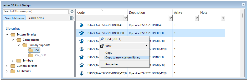
The program next asks for a description of the new library. Enter a suitable name and click OK. In this example, we use My library. Your new personal library then appears in the browser (Custom libraries > Components > Primary supports > My library), and the copied primary support is shown in the browser.
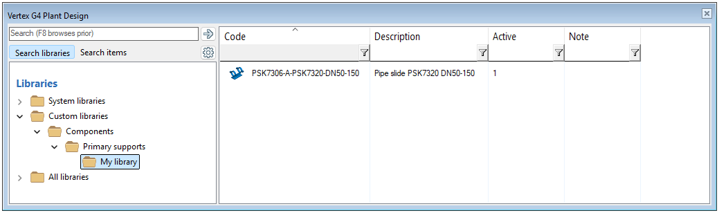
Your library's data is located in File Explorer under \custom\complibs\. The library folder is initially named with a combination of numbers and letters, for example 90916599-419e-4d5d-95a9-31a354412e2d. You can rename it descriptively, but close Libraries before renaming it. NOTE! Spaces are not allowed in folder names, so name the library folder, for example, My_library. The folder can also have any other name; this does not affect the name of the folder from which primary supports are eventually added to the pipeline.
You can edit the copied primary support's data either by double-clicking its row in the browser or by selecting the row > right-click > Properties. The Primary Supports window opens. All fields are now editable.
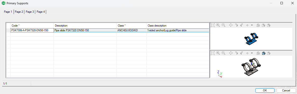
In this example, the support data is changed as follows:
-
Size range is DN50-125.
-
Only stopper type A can be added to the support.
-
The support installation angle is 45 degrees by default.
-
The support will henceforth be found under Modified PSK > Slide supports.
Required changes to the support data:
Code: PSK7306-A-PSK7320-DN50-150 >> PSK7306-A-PSK7320-DN50-125
Description: Slide support PSK7320-DN50-150 >> Slide support PSK7320-DN50-125
Stoppers: PSK7362-A1|PSK7362-A2|PSK7362-B1|PSK7362-B2|PSK7362-C1|PSK7362-C2 >> PSK7362-A1|PSK7362-A2
DN max.: 150 >> 125
Parameters: ANG=0 >> ANG=45.
Folder: /PSK/Slide/ >> /Modified PSK/Slide supports/
The changes are saved when you close the Primary Supports window with OK. You can still cancel the changes by leaving the window with Cancel. To view the primary support in its new personal library, start Add primary support and select to the pipe:
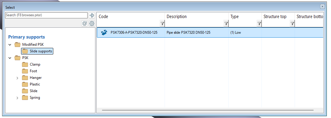
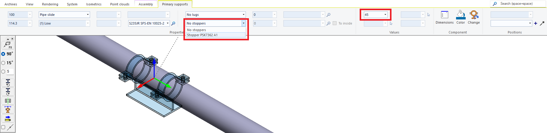
By copying supports from an existing library, you can create your own version of a primary support found in the standard library. This is the simplest way to begin creating your own library.
How to create a custom primary support assembly using components made by Vertex
Next, we explain how to build your own primary support assembly using parts created by Vertex and available in the standard component library. In this example, we build the hanger support PSK7340-YK1-AK1, which is already included in the standard library, but you can freely create different variations from the existing parts. Hanger supports are easiest to assemble from the bottom up, starting with the clamp.
Assembly modelling
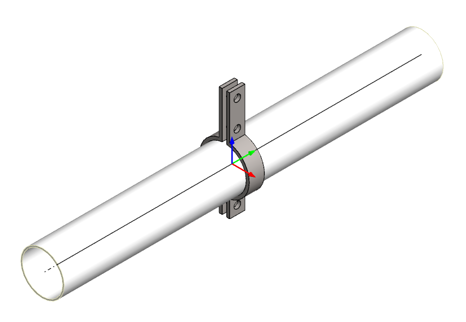
Create a new assembly. Give it a suitable identifier and save it as a file in an appropriate location. In the assembly, draw a piece of pipe of a suitable size along the Y-axis (green arrow) and place the pipe's midpoint at the assembly origin. In this example, a suitable pipe size is DN 100.
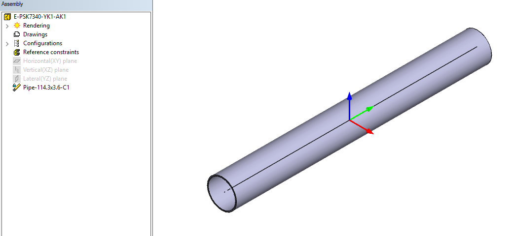
Add a new local sub-assembly to the assembly you created. Name the sub-assembly, for example, ASSEMBLY. In the sub-assembly properties, change the assembly to a pipe assembly: select ASSEMBLY in the assembly tree > right-click in the work window > Properties > Activate the check-box Pipe assembly > OK.
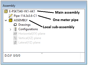
First add the hanger support clamp to the sub-assembly: right-click in the work window > Add… > Component... > the Select component window opens. The clamps are in the component library under Standard > Plant > Primarysupports > Clamps. Select hanger clamp PSK7308 and select the pipe. Position the clamp at the pipe midpoint.
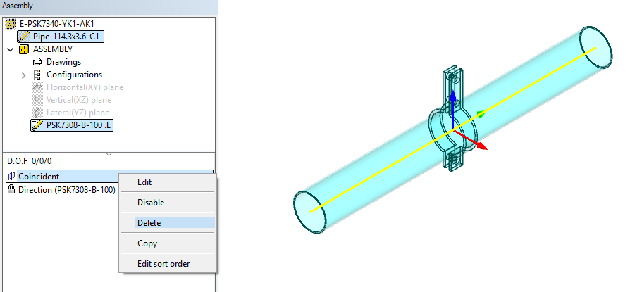
Delete the coincident constraint between the pipe and the clamp. At the bottom of the assembly tree, you can see all assembly constraints. Select Coincident > right-click > Delete. You can then hide the pipe. The clamp automatically receives an Direction constraint from the pipe, which helps position the clamp using constraints.
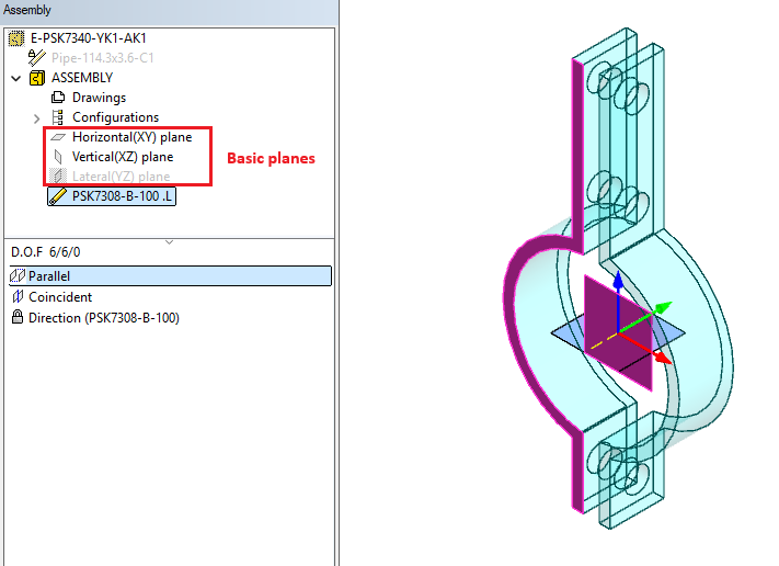
Restore the main planes XY, XZ, and YZ of the ASSEMBLY sub-assembly. Make the planes visible by double-clicking them in the assembly tree. Add a coincident constraint between the midpoint of the clamp's centerline and the assembly origin. Add a parallel constraint between the main plane XZ and the surface in the corresponding plane of the clamp (see image below).
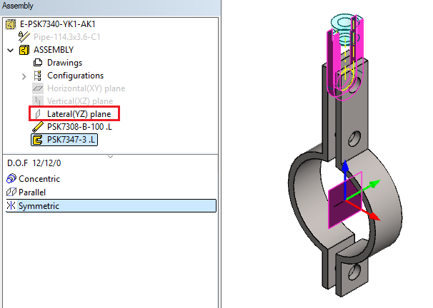
Next, add and position the eye nut in the assembly: right-click in the work window > Add… > Component... > the Select component window opens. The hanger support parts are in the component library under Standard > Plant > Primarysupports > Hangers. At the end of the list, find nut model PSK7347. For this pipe size, the correct load class is 3, so select size PSK7347-3 from the dimension table. Rotate the nut once by 90 degrees around its vertical axis (blue arrow) before placing it near the clamp in the assembly.
Position the eye nut using, for example, the following constraints:
-
Make the clamp's uppermost screw hole and the corresponding feature of the eye nut concentric.
-
Make a surface parallel to the XY plane on each part parallel to the other.
-
Use the main plane YZ to position the nut symmetrically.
The final part to add from the component library is upper attachment B: right-click in the work window > Add… > Component... > the Select component window opens. The hanger support parts are in the component library under Standard > Plant > Primarysupports > Hangers. At the end of the list, find support model PSK7344. For this pipe size, the correct load class is 3, so select size PSK7344-3 from the dimension table. Place the support above the clamp and nut.
Position the support using, for example, the following constraints:
-
Dimension the support from its top surface to the assembly's XY main plane using a Distance constraint with value 600 and formula LEN.
-
Make the support hole and the hole in the eye bolt's hanger rod concentric.
-
Add an Angle constraint for the upper attachment using the XZ main plane and the support's front surface. Set the angle to 0 and the formula to ANG.
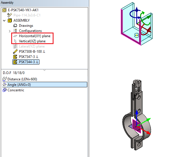
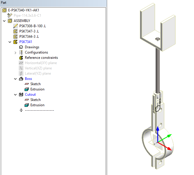
The last step with modelling is to model the hanger rod in the assembly. Because it is a variable part, it must be modelled as a local part. The same applies to a cross beam. Start by creating a part model for the ASSEMBLY sub-assembly, with identifier PSK7341, and make it local. Sketch a circle on the part model's XY plane, concentric with the origin. Dimension the circle diameter to 16 and assign the formula M. Extrude the hanger rod to the horizontal surface of the support. Remove the section at the lower end of the rod that ends at the round auxiliary plane of the eye nut by sketching a circle on the lower end and extruding with material removal up to the selected surface. Both extrusions are linked to external geometry, which is why the part and its features are shown in blue text in the tree.
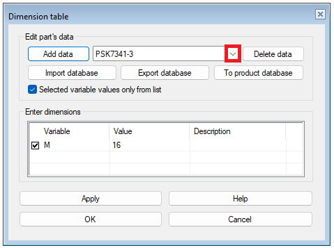
The final step is to add the dimensions for the rods so that the assembly varies correctly for all load classes. Open the part model's dimension table: right-click in the work window > Dimension table… > the dimension-table dialog opens. Add the identifiers and dimensions according to standard PSK 7341. The identifier must use the specified format so that the program can vary it correctly when the primary support is added. Use the following format for the hanger rod: PSK7341-1, where the number indicates the load class. The hanger rod has six load classes, with thread sizes from class one to class six: M10, M12, M16, M20, M24, and M30. Start by entering identifier PSK7341-3 in the identifier field and click Add data. Then select Selected variable values only from list. Enter the data for the remaining rods in the dimension table one at a time. First enter the identifier (PSK7341-1), define the thread size (10), and click Add data. Repeat until all six rods are visible in the identifier drop-down list (red box in the image). Close the window with OK to save the data. The hanger rod is now ready. Return to the ASSEMBLY assembly level (OK).
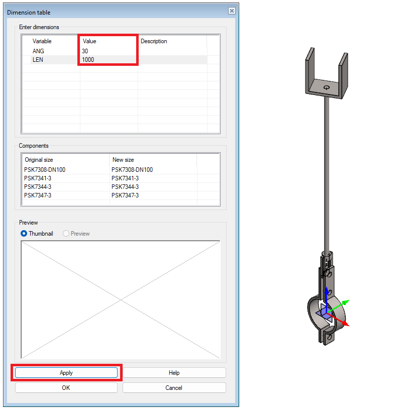
The assembly modelling is now complete. Test that the formulas work. Open the Dimension table. Change the values of ANG and LEN in the dimension table. Check that the model varies when you click Apply. If the hanger rod extends with the movement of the support and the upper attachment rotates according to the angle, the model is correct.
Saving to the library and entering the data
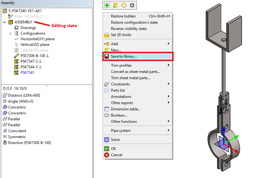
First, make sure that the ASSEMBLY sub-assembly is in edit mode. After verifying this, right-click in the work window and select Save to library… from the context menu. The program recognizes that this may be a primary support and automatically suggests \shared\components\Plant\Primarysupports\ as the save location. You can freely create subfolders in this folder. Enter a filename for the assembly and click Save.
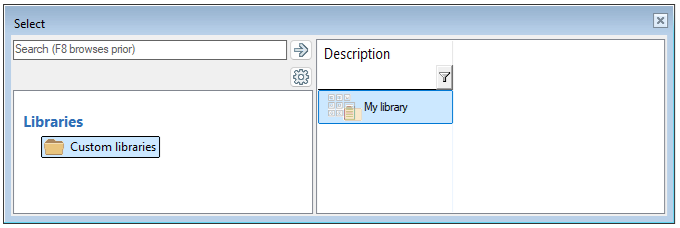
Select the library where you want to save the primary support and double-click the library name. In this example, the library already created is used: Custom libraries > My library.
The next step is to enter the support data. The meanings of the fields were explained earlier in this instruction. The list already contains supports previously added to the library, which can make it easier to complete missing data for the new support.
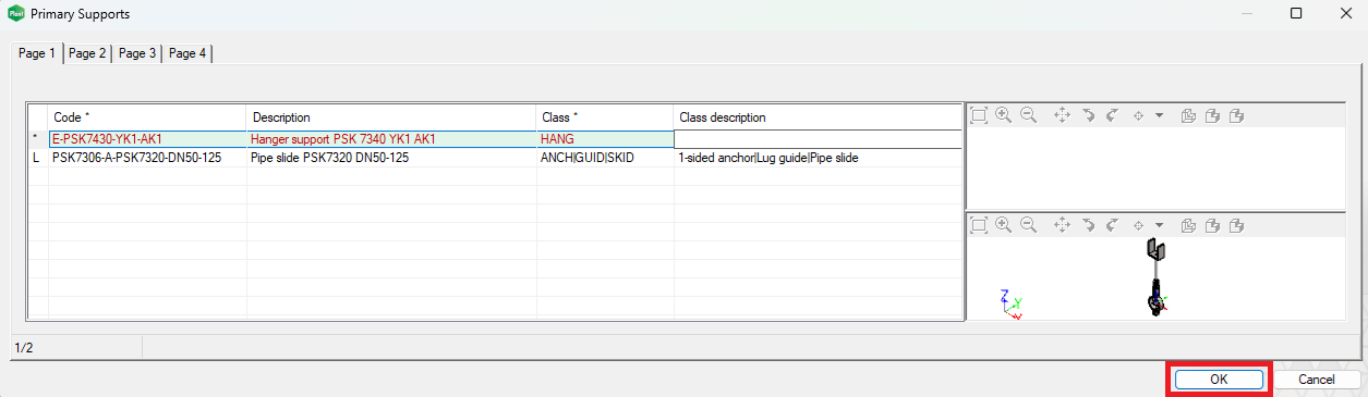
The data entered on pages 1–4 in this example is:
-
Page 1: Code = E-PSK7340-YK1-AK1; Description = Hanger support PSK7340 YK1 AK1; Class = HANG
-
Page 2: Structure top = YK1; Structure bottom = AK1
-
Page 3: DN min. = 10; DN max. = 500; Load class = DN10-1-2|DN50-2-3.5|DN100-3-8|DN350-4-15|DN500-5-22; Parameters = LEN=?|ANG=0
-
Page 4: Color = VxColor_209; Folder = /My library/Hanger supports/
The data is saved when you close the Primary Supports window with OK. You can still cancel the save by leaving the window with Cancel. You can then close the support's so-called working model.
Using your own support
To view the new primary support in your own library, start Add primary support and select the pipe:
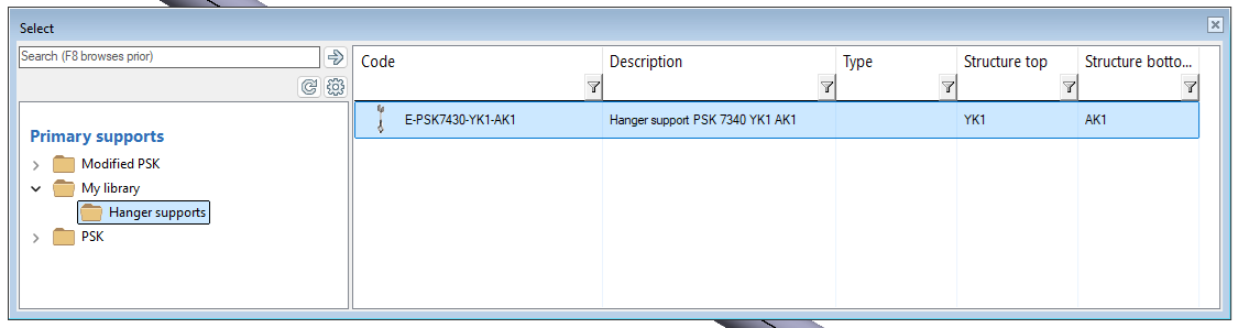
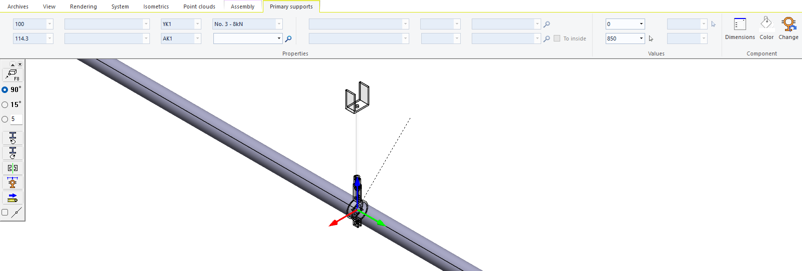
Using existing standard-library models, you can build primary support assemblies that are not included in the standard library when needed.
How to create a completely custom support
You can also model the parts used in support assemblies yourself from scratch. Earlier sections described the modelling and data requirements for different types of parts.
Pay particular attention to the following:
-
Model the parts in their proper positions.
-
Use the exact spelling of the identifiers specified in the dimension tables, for example, CLAMP-DN50.
-
Use the formula values specified above, for example, LEN and ANG.
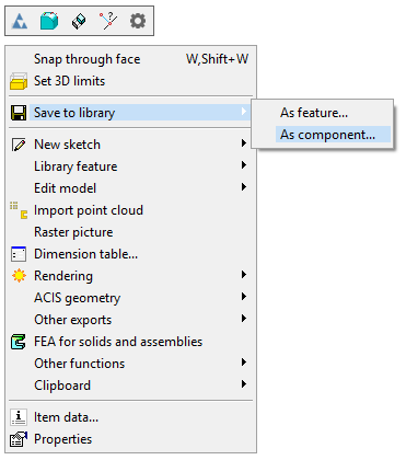
Save the parts you have modelled to the component library as usual: in the part model's work window, right-click and select Save to library > As component… from the context menu. Components are saved in \shared\components\, where you can freely create the sub-folders you need.
Building and adding primary support assemblies to the library proceeds as described in the previous section. Using self-created primary supports also works as explained above. With the new library technology, you can create exactly the library you need!