
This guide is valid till version 2023 (29.0.XX) of Vertex G4Plant.
We have renewed the library technique for primary supports in version 2024 (30.0.0).
General
It has been impossible to add your primary supports to the default library in Vertex G4Plant.
You can now model or download primary supports and save them to the pipe component library by following this guide. By doing so you will receive these benefits:
-
The primary support automatically turns parallel to the pipe when added.
-
When the primary supports are selected, only supports of the active pipe size are displayed.
-
The support parts list information is automatically obtained from the pipe component library and the pipe options database.
How to Save Primary Support to Pipe Component Library
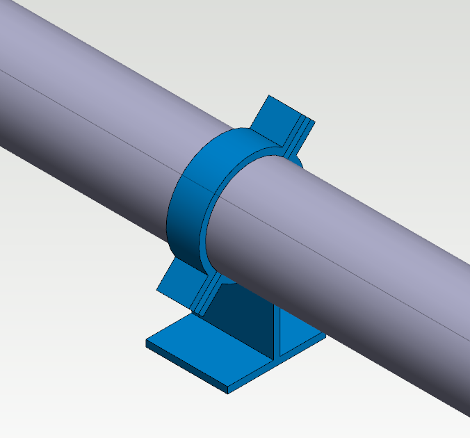
1A. Model the variable primary support
Model your part by using feature-based modeling tools.
NOTE! The origin of the model must be in the middle of the support and on the centerline of the pipe. The handle in the picture above is a good exemple of this setup.
Check out Basics and Advanced, if you need help at this point.
Stopper and lugs can be modeled so that you can change their number and position when the support is added to the pipeline. The check-box Selected variable values only from list must be left unchecked in the Dimension table for this to work.
1B. Convert your downloaded model to the Vertex model
Download the model of the primary support, for example from the supplier's 3D library.
Check out Basics, if you need help at this point.
Please activate the full-screen mode to see the video properly. Exit the full-screen mode by clicking the Esc button.
2. Add the centerline and handle to the model
The centerline and handle of the primary support are different from the normal case of a pipe component.
The right mouse button opens the context-sensitive menu > New Sketch > Pipecomp. centerlines and handles > You will enter to the Sketch 3D mode.
Select the function Two-Point Line from the group Lines > Draw the centerline. The length itself does not matter as long as the other end of the line is in the middle of the support (at the origin). In the video, the centerline is drawn from the outer edge of the clamp to the center of the support.
Click OK after you have finished sketching the centerline.
The next step is to add Insertion points > Add > Show the handle point from the middle of the support > Define the handle's Code > Enable the check-box Pipe connection and define Formula of diameter (pipe od) > Confirm the handle details by clicking OK > Click Exit after you have completed.
Make sure that Show Reference Geometry is enabled if you don't see your centerline with the handle linkage.
Please activate the full-screen mode to see the video properly. Exit the full-screen mode by clicking the Esc button.
3. Save the primary support to the pipe component library
Rotate the pipe component into a position which presents the component well. This will be the thumbnail of the part in the browser.
The right mouse button opens the context-sensitive menu >Save To Library > As Component...
Save the pipe component to the folder /shared/pipelibrary/ (own pipe components) > Create a subfolder to the folder /shared/pipelibrary/ if needed, for example, Supports.
Name the file > Save.
Please activate the full-screen mode to see the video properly. Exit the full-screen mode by clicking the Esc button.
4. Define the selection data of the primary support
Check out for further information of pipe component database's (d_PIPECOMPONENTS) fields by clicking the Help button. You can locate the Help button from the lower right corner of the database window.
Fill the selection data of the pipe component. The fields marked with an asterisk (*) are mandatory.
-
Code - The unique identifier (item code) of the pipe component.
-
Class - Select from the drop-down menu. The correct options are in the folder Support.
-
Type -The description of the SKEY symbol. If you select the class from the dropdown menu, the program adds automatically the description to the Type field.
-
Description - The clear and informative description of the pipe component.
-
Main Group: The primary support belongs to the group "1 pipe component".
-
DN - The nominal size of the pipe component.
-
Diameter - The outer or inner diameters of pipe. The diameter (outer or inner) of the connective pipes of the pipe component. The value of the diameter must be the same as the Value of diameter of the connecting handle or the value specified by the Formula of diameter.
-
Parameters - The parameters of variable pipe component. Leave this field empty, if the component does not have any variables.
-
Classes - Leave this field empty.
-
File - The model of the pipe component.
-
Please check the Help for further information.
With the program's default settings, the Description and Material fields appear in the parts list of the isometric drawing.
If the primary supports include additional parts, such as stoppers, that you want to include in the parts lists, add them to the pipe options database. See Advanced for detailed instructions. You can add these unmodeled sub-parts already when defining the selection data, or later, as in the related video.
Click OK from the lower right corner after you have filled the data.
The pipe component is now ready. You can add it from the pipe component library.
For more detailed instructions, see Advanced for how to add selection data for multiple primary supports to the database using Excel, for example.
Selection data
Please activate the full-screen mode to see the video properly. Exit the full-screen mode by clicking the Esc button.
Unmodeled sub-parts
Please activate the full-screen mode to see the video properly. Exit the full-screen mode by clicking the Esc button.
5. How to use your primary support
When you make primary support according to the instructions above, the principle of operation is as follows:
-
The primary support automatically turns parallel to the pipe when added.
-
When the primary supports are selected, only supports of the active pipe size are displayed.
-
The support parts list information is automatically obtained from the pipe component library and the pipe options database.
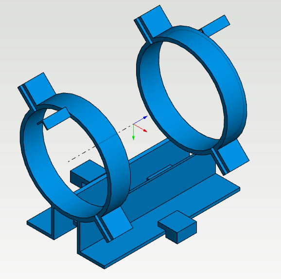
Download the example support from here. The model contains also stoppers and lugs. Save the package to your workstation and then drag and drop it to G4Plant's working window. The program adds two new rows to the pipe component database. Refresh the Vertex browser afterward.
The downloadable sample support works in practice as follows:
-
Add the support as a pipe component. You can add it while routing the pipeline, but it works best when you add it to an existing pipeline.
-
You can locate the supports from the pipe component browser under the folder Own and Supports.
-
Select the support from the browser and then click the centerline of the pipe.
-
The support's item data contains also the item data of stoppers and lugs.
-
The primary support and unmodeled sub-parts are listed under the topic Supports in the isometric drawing's parts list.
-
There is no coincident constraint between the support and the pipeline. However, if desired, such can be manually added between the support and the centerline of the pipe. The isometric drawing does not require a coincidence.
-
You can change the dimension table of the example support when it's on the pipeline. The program does not change the number of stoppers in the item data if you change the number of them in the dimension table. You fix the item data manually or create separate models by the number of the stoppers (2, 4, 8...).
Please activate the full-screen mode to see the video properly. Exit the full-screen mode by clicking the Esc button.