
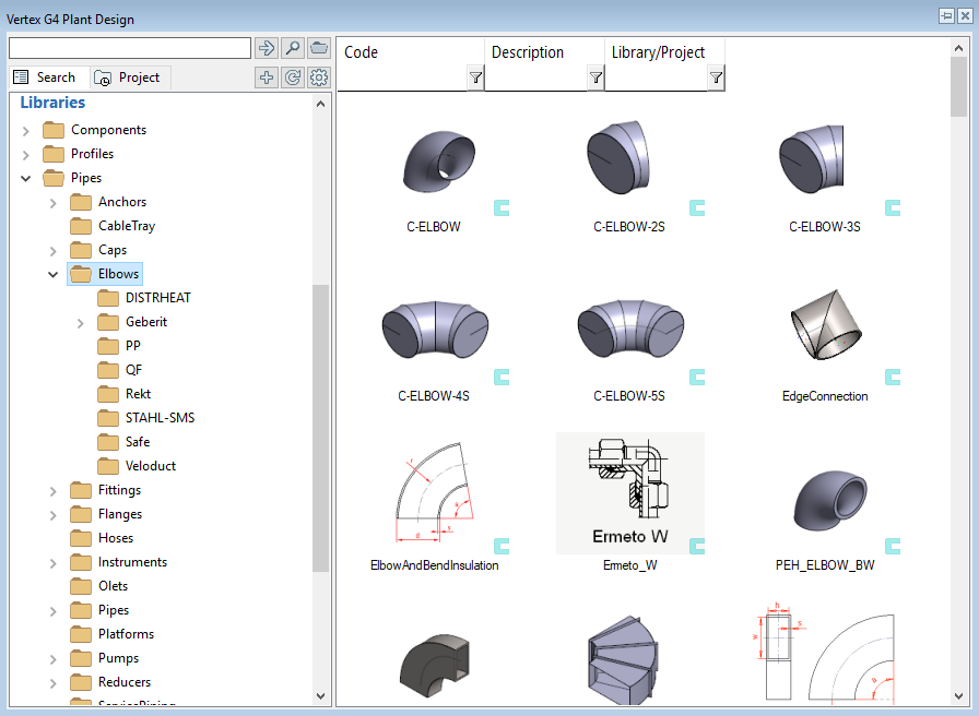
Check out also Basics.
Dimension drawing of variable pipe component
You can make a dimension drawing for the variable pipe component. The drawing is visible when you are adding the pipe component to your assembly from the browser and when you are on Page 2 on the pipe component database view.
The dimension drawing will help you with the maintenance of the pipe component library but it isn't necessary.
Make the dimension drawing either with 2D drawing tools of Vertex or use image processing program.
Save the drawing with the same name as the pipe component including a postfix "_2d", for example, "Gasket-PN40-H2_2d". The usual drawing sizes are 236X236, 270X200, and 270X270 pixels.
The supported file formats are bmp and jpg from which the later is recommended.
Copy and paste the dimension drawing to the same folder where the pipe component is, for example, /shared/pipelibrary/Gaskets/.
Done.
Unmodeled sub-parts
1. General
Save the pipe component to the pipe component library as a part model whenever it's possible. The maintenance task of the pipe assemblies is more time consuming than with the pipe components.
You can model the component, which consists of two pieces, for example, as a one-piece model. The one-piece model can contain the item data of the second unmodeled part. The item data is visible in the parts lists.
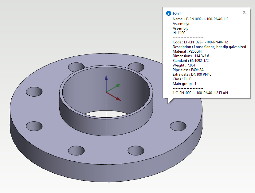
The loose flange model (fl_loose) from the default pipe component library is a very good example of this method. The flange and collar are modeled as the one-piece model. The item data of the flange is stored to the database (d_PIPECOMPONENTS) and the item data of the collar is stored to the database (d_PIPEOPTIONS).
One pipe component can have N pieces of unmodeled sub-parts.
You can check the sub-parts of the pipe component from your assembly by viewing its item data.
2. To single pipe component
You can add the unmodeled sub-part either during the saving the pipe component or afterward.
During the saving:
-
Define the selection data of the pipe component.
-
Click the button Add. comp.
-
This will open the pipe options database.
-
Insert a new row to the database > Select an empty row underneath the filter row > Right mouse button > Insert row before.
-
Fill the item data of the sub-part. The most important fields are listed below:
-
Code - The (item) code of the sub-part
-
Mother Code - The code of the mother component.
-
Description - The clear and informative description of the sub-part.
-
Quantity - The number of sub-parts.
-
-
Close the Component Options window by clicking OK button to save your changes.
-
Close the Components window by clicking OK button
Afterward:
-
Open the pipe component database > Sheet System > Databases > Components > Components (search) > Use the search if wanted.
-
The database view is now open > Select the correct pipe component > Click the button Add. comp. > Fill the data by following the steps described above.
The pipe component has now unmodelled sub-parts in the item data when you add it to the assembly.
Please activate the full-screen mode to see the video properly. Exit the full-screen mode by clicking the Esc button.
3. To multiple pipe components
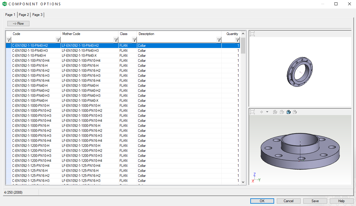
You can also add the unmodeled sub-parts to several different pipe components by using the specific database tools.
Prepare the data in Excel, for example. You need at least the codes of the sub-part and mother component, description of the sub-part and the quantity.
-
Open the pipe options database > Sheet System > Databases > Components > Component options.
-
You can use the filter to hide unnecessary lines from the database.
-
Select one row from the database > Right mouse button > Export > Modify in Excel and import back > This will transfer the visible lines to the Excel for further editing.
-
Insert the new rows to the end of the list and make sure that the columns match.
-
Save the Excel > Reply "Yes" to the Excel's format question > Close Excel > This will initiate the transfer back to the database.
-
The program notifies when the transfer is completed > Close the window by clicking OK.
-
You can now see the added rows with blue font. Save the changes and close the database window by clicking OK
The pipe component has now unmodelled sub-parts in the item data when you add it to the assembly.
Please activate the full-screen mode to see the video properly. Exit the full-screen mode by clicking the Esc button.
How to save variable pipe component to pipe component library with dimension table
1. Model the variable part
Create a new part: Sheet Archives > Create new document > Part > OK.
You can save your part as a file or to the archive, for example, to the folder picts.
Model your part by using feature-based modeling tools.
Define Formulas for variable dimensions. You are going to need these when you create a Dimension table to your part and Parameters to the pipe component database. The Formulas can contain basic mathematical calculation: plus, minus, multiply, and divide. The Formulas can contain also several variables, for example, M1-M2*2.
Make sure that all your sketches are fully defined when you model your variable part. The variable part might not be working properly if it contains undefined sketches.
Please check the page Special features, if you are modeling one of the following pipe components.
-
Elbow
-
Valve with handle
-
Check valve (Non-return valve)
-
Olet
-
Flange
Please activate the full-screen mode to see the video properly. Exit the full-screen mode by clicking the Esc button.
2. The dimension table of the part
The right mouse button opens the context-sensitive menu > Dimension Table...
Type the code of the part to the field and click the button Add data.
Enable the check-box Selected variable values only from list.
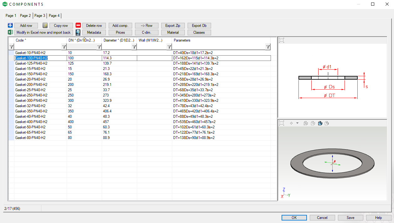
Prepare the data of the variants in Excel, for example. You need the code and the dimensions data.
The next step is to add all variants to the dimension table > Export database > Save the data in a suitable format and into a suitable folder > Insert all variants to the file > Import database > The part model contains now all variants.
The attached video shows the previous procedure by using an XML file.
It's a good idea to test the variable model > Select different variants from the list and click Apply > Start by selecting a small size, then a big size, and then the small size again > This will verify that the geometry of the variable part is working properly.
Close the Dimension Table by clicking OK.
NOTE! The file size of the pipe component increases as the list of variants grow.
Please activate the full-screen mode to see the video properly. Exit the full-screen mode by clicking the Esc button.
4. Save the part to the pipe component library
Rotate the pipe component into a position which presents the component well. This will be the thumbnail of the part in the browser.
The right mouse button opens the context-sensitive menu >Save To Library > As Component...
Save the pipe component to the folder /shared/pipelibrary/ (own pipe components) > Create a subfolder to the folder /shared/pipelibrary/ if needed, for example, Valves.
Name the file > Save.
Please activate the full-screen mode to see the video properly. Exit the full-screen mode by clicking the Esc button.
5. Define the selection data of the pipe component
Check out for further information of pipe component database's (d_PIPECOMPONENTS) fields by clicking the Help button. You can locate the Help button from the lower right corner of the database window.
Fill the selection data of the pipe component. The fields marked with an asterisk (*) are mandatory.
-
Code - The unique identifier (item code) of the pipe component.
-
Class - The four-letter definition of the SKEY symbol defined by ISOGEN. Select from the drop-down menu.
-
Type -The description of the SKEY symbol. If you select the class from the drop-down menu, the program adds automatically the description to the Type field.
-
Description - The clear and informative description of the pipe component.
-
Main Group: Each pipe component belongs to one main group. There are four main groups: "1 pipe component", "2 duct component", "3 cable ladder component" and "4 platform or stair component".
-
DN - The nominal size of the pipe component.
-
Diameter - The outer or inner diameters of pipe. The diameter (outer or inner) of the connective pipes of the pipe component. The value of the diameter must be the same as the Value of diameter of the connecting handle or the value specified by the Formula of diameter.
-
Wall - The wall thicknesses of pipe. You do not need to define the wall thickness to those components, which do not have wall thickness like valves, for example.
-
Parameters - The parameters of variable pipe component. Leave this field empty, if the component does not have any variables.
-
Classes - Fill all those pipe classes to the pipe component, where you want to use the component. Separate the classes with the vertical line (|). The component is visible in every class if you leave this field empty. You can also define the classes from the drop-down menu. Select the proper classes by pressing the Ctrl button and then selecting them from the list.
-
File - The model of the pipe component.
-
Please check the Help for further information.
You can use the functionalities of the database window to fill the data to the fields. Open the Help to find further information on these tools.
Click OK from the lower right corner after you have filled the data.
The pipe component is now ready. You can add it from the pipe component library.
Please activate the full-screen mode to see the video properly. Exit the full-screen mode by clicking the Esc button.
How to save variable pipe component to pipe component library with Excel
1. Model the variable part
Create a new part: Sheet Archives > Create new document > Part > OK.
You can save your part as a file or to the archive, for example, to the folder picts.
Model your part by using feature-based modeling tools.
Define Formulas for variable dimensions. You are going to need these when you create a Dimension table to your part and Parameters to the pipe component database. The Formulas can contain basic mathematical calculation: plus, minus, multiply, and divide. The Formulas can contain also several variables, for example, M1-M2*2.
Make sure that all your sketches are fully defined when you model your variable part. The variable part might not be working properly if it contains undefined sketches.
Please check the page Special features, if you are modeling one of the following pipe components.
-
Elbow
-
Valve with handle
-
Check valve (Non-return valve)
-
Olet
-
Flange
Please activate the full-screen mode to see the video properly. Exit the full-screen mode by clicking the Esc button.
2. The dimension table of the part
The right mouse button opens the context-sensitive menu > Dimension Table...
It's a good idea to test the variable model. Use the dimensions from different variants. Small size, big size, small size, for example.
Type the code of one variant to the field and click the button Add data.
Enable the check-box Selected variable values only from list.
Close the Dimension Table by clicking OK.
Please activate the full-screen mode to see the video properly. Exit the full-screen mode by clicking the Esc button.
3. Add the centerline(s) and handles to the model
The right mouse button opens the context-sensitive menu > New Sketch > Pipecomp. centerlines and handles > You will enter to the Sketch 3D mode.
Select one of these functions Two-Point Line, Polyline, Arc with Center and Radii Points or Arc with Three Points from the group Lines >
-
Pipe component with two handles > Sketch the centerline from the handle location to the handle location.
-
Pipe component with three handles > Sketch the first centerline from the handle location to the handle location and the second centerline from the handle location to the first centerline.
-
Check the guide (F1) with the topic "Basics - Component's center line and handles" for further information.
Click OK after you have finished sketching the centerline.
The next step is to add Insertion points > Add > Show the handle points from the ends of the centerline(s) > Define the handle's Code > Enable the check-box Pipe connection >Select a connection type if needed (e.g. "FL Flanged") > Type or select Value of diameter > Repeat to all insertion points > Click Exit after you have completed.
Make sure that Show Reference Geometry is enabled if you don't see your centerline with the handle linkages.
You can edit the Insertion points afterward if needed > Right mouse button > Other functions > Edit Named Elements...
Please activate the full-screen mode to see the video properly. Exit the full-screen mode by clicking the Esc button.
4. Save the part to the pipe component library
Rotate the pipe component into a position which presents the component well. This will be the thumbnail of the part in the browser.
The right mouse button opens the context-sensitive menu >Save To Library > As Component...
Save the pipe component to the folder /shared/pipelibrary/ (own pipe components) > Create a subfolder to the folder /shared/pipelibrary/ if needed, for example, Valves.
Name the file > Save.
Please activate the full-screen mode to see the video properly. Exit the full-screen mode by clicking the Esc button.
5. Define the selection data of the pipe component
Check out for further information of pipe component database's (d_PIPECOMPONENTS) fields by clicking the Help button. You can locate the Help button from the lower right corner of the database window.
Fill the selection data of the pipe component. The fields marked with an asterisk (*) are mandatory.
-
Code - The unique identifier (item code) of the pipe component.
-
Class - The four-letter definition of the SKEY symbol defined by ISOGEN. Select from the drop-down menu.
-
Type -The description of the SKEY symbol. If you select the class from the drop-down menu, the program adds automatically the description to the Type field.
-
Description - The clear and informative description of the pipe component.
-
Main Group: Each pipe component belongs to one main group. There are four main groups: "1 pipe component", "2 duct component", "3 cable ladder component" and "4 platform or stair component".
-
DN - The nominal size of the pipe component.
-
Diameter - The outer or inner diameters of pipe. The diameter (outer or inner) of the connective pipes of the pipe component. The value of the diameter must be the same as the Value of diameter of the connecting handle or the value specified by the Formula of diameter.
-
Wall - The wall thicknesses of pipe. You do not need to define the wall thickness to those components, which do not have wall thickness like valves, for example.
-
Parameters - The parameters of variable pipe component. Leave this field empty, if the component does not have any variables.
-
Classes - Fill all those pipe classes to the pipe component, where you want to use the component. Separate the classes with the vertical line (|). The component is visible in every class if you leave this field empty. You can also define the classes from the drop-down menu. Select the proper classes by pressing the Ctrl button and then selecting them from the list.
-
File - The model of the pipe component.
-
Please check the Help for further information.
Export the data of the defined pipe component to Excel > Select the row > Right mouse button > Export > To formatted Excel-file > Select "Common data transfer" > OK > Save the file to a suitable folder with a suitable name.
This file will serve as a template for the other variants of the variable pipe component.
Close the database view by clicking OK.
Please activate the full-screen mode to see the video properly. Exit the full-screen mode by clicking the Esc button.
6. Insert the pipe components with Excel
Prepare the data of the pipe components in Excel. Use Excel's functions to create parameter data, for example. The attached video shows how you can create codes and parameters for your pipe components by using the Excel tools.
Return to the template Excel which you made in the previous phase. Fill the template with the pipe component data with the help of the pipe component in the template and your pipe component data.
Open the pipe component database after you have finalized the template > Sheet System > Databases > Components > Components (search) > Search with the code of the pipe component which you made in the previous phase.
Select the row from the database > Click Modify in Excel and import back > This will export the visible rows from the database to Excel for further modification.
Insert the new rows to the end of the list and make sure that the columns match.
Save the Excel > Reply "Yes" to the Excel's format question > Close Excel > This will initiate the transfer back to the database.
The program notifies when the transfer is completed > Close the window by clicking OK.
You can now see the added rows with blue font. Save the changes and close the database window by clicking OK
The new variants of the pipe component are now ready. You can add them from the pipe component library to your assembly.
Please activate the full-screen mode to see the video properly. Exit the full-screen mode by clicking the Esc button.
Check out also Basics.