
Check out also Advanced.
General
Databases
The name of the pipe component database is d_PIPECOMPONENTS. This database defines the pipe component ID, selection information, and component model file.
The name of the pipe option database is d_PIPEOPTIONS. This database defines unmodeled sub-parts for the pipe component, such as a collar of a loose flange. You can find more information about the unmodeled sub-parts on the Advanced page.
You can locate the standard databases from here /system/dbases/.
The program will copy these databases from a system folder to a folder /custom/dbases/ when you make the first modification to the specific database. For example, adding a new pipe component to the library will launch the copy function.
All your further modifications to these databases are saved to the databases in the custom folder after this point.
Note! New pipe components with their unmodelled sub-parts that come with main versions and update packages do not automatically migrate to databases in the custom folder. Completing databases with new database rows requires user intervention. Learn more about these tools on the Maintenance page.
Note! Do not make changes to the databases in the system folder directly. You will lose these changes if the update package comes with updates to those databases.
Pipe component models
Models of the pipe component library included with the program can be found here /system/pipelibrary/.
Save your pipe components here /shared/pipelibrary/.
You are free to create subfolders for your pipe components, for example /shared/pipelibrary/Valves/.
Note! Do not modify pipe component models in the system folder directly. You will lose these changes if the update package comes with updates for those models
If you want to modify the existing models, copy them first from the folder /system/pipelibrary/ to the folder /shared/pipelibrary/. Make changes to the models in the shared folder.
Different types of pipe components
Pipe component
-
Vertex model without a dimension table.
-
Part model, which is imported from another file format, for example, STEP file.
You can insert either a part you have modeled or a downloaded SAT, IGES, or STEP file to your pipe component library. The SAT file is recommended.
Variable pipe component
-
Vertex model with a dimension table.
You can model a variable model and save it to the pipe component library.
Pipe assembly
-
Vertex assembly which contains at least one handle linkage.
Make an assembly which contains at least one handle linkage. It should have one pipe or pipe component as a minimum. Save it to the pipe component library. The assembly must be defined as Pipe Assembly.
How to save pipe component to pipe component library
1A. Model the part
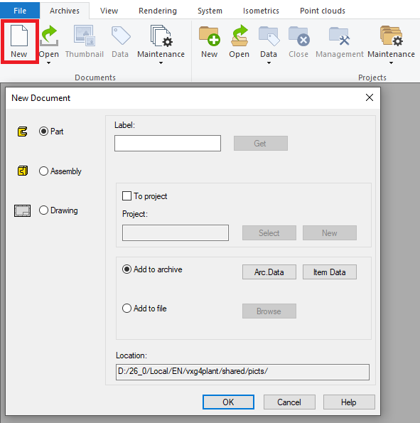
Create a new part: Sheet Archives > Create new document > Part > OK.
You can save your part as a file or to the archive, for example, to the folder picts.
Model your part by using feature-based modeling tools.
Please check the page Special features, if you are modeling one of the following pipe components.
-
Elbow
-
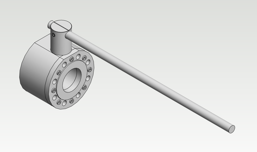
Valve with handle
-
Check valve (Non-return valve)
-
Olet
-
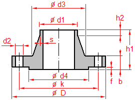
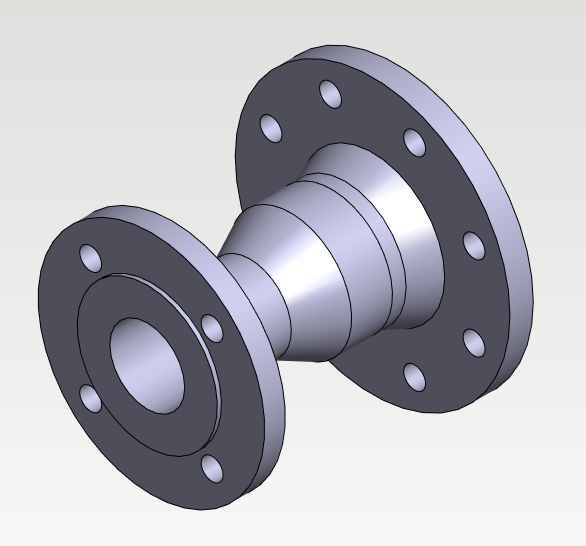
Flange
1B. Convert your downloaded model to the Vertex model
Import your downloaded model to Vertex: File > Import > Select the file > Open.
The other option is that you just drag and drop your file to a working window of Vertex.
Enable the check-box Heal parts when the program asks about import options.
The converted model must be a one-part model in Vertex if you want to use it as a pipe component.
Sometimes your converted model ends up being an assembly in Vertex. You didn't have a possibility to convert your model as one part during the conversion. To overcome this situation you need to convert your Vertex model to SAT format. Import this SAT file back to Vertex and now you can choose the option Import as one part from the conversion dialog. Now you have a model which you can use as a pipe component.
Please check the page Special features, if you are converting one of the following pipe components.
-
Elbow
-
Valve with handle
-
Check valve (Non-return valve)
-
Olet
-
Flange
Please activate the full-screen mode to see the video properly. Exit the full-screen mode by clicking the Esc button.
2. Add the centerline(s) and handles to the model
The right mouse button opens the context-sensitive menu > New Sketch > Pipecomp. centerlines and handles > You will enter to the Sketch 3D mode.
Select one of these functions Two-Point Line, Polyline, Arc with Center and Radii Points or Arc with Three Points from the group Lines >
-
Pipe component with two handles > Sketch the centerline from the handle location to the handle location.
-
Pipe component with three handles > Sketch the first centerline from the handle location to the handle location and the second centerline from the handle location to the first centerline.
-
Check the guide (F1) with the topic "Basics - Component's center line and handles" for further information.
Click OK after you have finished sketching the centerline.
The next step is to add Insertion points > Add > Show the handle points from the ends of the centerline(s) > Define the handle's Code > Enable the check-box Pipe connection >Selec a connection type if needed (e.g. "FL Flanged") > Type or select Value of diameter > Repeat to all insertion points > Click Exit after you have completed.
Make sure that Show Reference Geometry is enabled if you don't see your centerline with the handle linkages.
You can edit the Insertion points afterward if needed > Right mouse button > Other functions > Edit Named Elements...
Please activate the full-screen mode to see the video properly. Exit the full-screen mode by clicking the Esc button.
3. Save the part to the pipe component library
Rotate the pipe component into a position which presents the component well. This will be the thumbnail of the part in the browser.
The right mouse button opens the context-sensitive menu >Save To Library > As Component...
Save the pipe component to the folder /shared/pipelibrary/ (own pipe components) > Create a subfolder to the folder /shared/pipelibrary/ if needed, for example, Valves.
Name the file > Save.
Please activate the full-screen mode to see the video properly. Exit the full-screen mode by clicking the Esc button.
4. Define the selection data of the pipe component
Check out for further information of pipe component database's (d_PIPECOMPONENTS) fields by clicking the Help button. You can locate the Help button from the lower right corner of the database window.
Fill the selection data of the pipe component. The fields marked with an asterisk (*) are mandatory.
-
Code - The unique identifier (item code) of the pipe component.
-
Class - The four-letter definition of the SKEY symbol defined by ISOGEN. Select from the drop-down menu.
-
Type -The description of the SKEY symbol. If you select the class from the dropdown menu, the program adds automatically the description to the Type field.
-
Description - The clear and informative description of the pipe component.
-
Main Group: Each pipe component belongs to one main group. There are four main groups: "1 pipe component", "2 duct component", "3 cable ladder component" and "4 platform or stair component".
-
DN - The nominal size of the pipe component.
-
Diameter - The outer or inner diameters of pipe. The diameter (outer or inner) of the connective pipes of the pipe component. The value of the diameter must be the same as the Value of diameter of the connecting handle or the value specified by the Formula of diameter.
-
Wall - The wall thicknesses of pipe. You do not need to define the wall thickness to those components, which do not have wall thickness like valves, for example.
-
Parameters - The parameters of variable pipe component. Leave this field empty, if the component does not have any variables.
-
Classes - Fill all those pipe classes to the pipe component, where you want to use the component. Separate the classes with the vertical line (|). The component is visible in every class if you leave this field empty. You can also define the classes from the dropdown menu. Select the proper classes by pressing the Ctrl button and then selecting them from the list.
-
File - The model of the pipe component.
-
Please check the Help for further information.
Click OK from the lower right corner after you have filled the data.
The pipe component is now ready. You can add it from the pipe component library.
Please activate the full-screen mode to see the video properly. Exit the full-screen mode by clicking the Esc button.
How to save variable pipe component to pipe component library
1. Model the variable part
Create a new part: Sheet Archives > Create new document > Part > OK.
You can save your part as a file or to the archive, for example, to the folder picts.
Model your part by using feature-based modeling tools.
Define Formulas for variable dimensions. You are going to need these when you create a Dimension table to your part and Parameters to the pipe component database. The Formulas can contain basic mathematical calculation: plus, minus, multiply, and divide. The Formulas can contain also several variables, for example, M1-M2*2.
Make sure that all your sketches are fully defined when you model your variable part. The variable part might not be working properly if it contains undefined sketches.
The example model in the video contains one dimension variable "d1" which doesn't affect to part's geometry. This construction line was made because now it is possible to define a proper variable for the handle linkage.
Please check the page Special features, if you are modeling one of the following pipe components.
-
Elbow
-
Valve with handle
-
Check valve (Non-return valve)
-
Olet
-
Flange
Please activate the full-screen mode to see the video properly. Exit the full-screen mode by clicking the Esc button.
2. The dimension table of the part
The right mouse button opens the context-sensitive menu > Dimension Table...
Type the code of the part to the field and click the button Add data.
Enable the check-box Selected variable values only from list.
Close the Dimension Table by clicking OK.
Please activate the full-screen mode to see the video properly. Exit the full-screen mode by clicking the Esc button.
3. Add the centerline(s) and handles to the model
The right mouse button opens the context-sensitive menu > New Sketch > Pipecomp. centerlines and handles > You will enter to the Sketch 3D mode.
Select one of these functions Two-Point Line, Polyline, Arc with Center and Radii Points or Arc with Three Points from the group Lines >
-
Pipe component with two handles > Sketch the centerline from the handle location to the handle location.
-
Pipe component with three handles > Sketch the first centerline from the handle location to the handle location and the second centerline from the handle location to the first centerline.
-
Check the guide (F1) with the topic "Basics - Component's center line and handles" for further information.
Click OK after you have finished sketching the centerline.
The next step is to add Insertion points > Add > Show the handle points from the ends of the centerline(s) > Define the handle's Code > Enable the check-box Pipe connection >Selec a connection type if needed (e.g. "FL Flanged") > Type or select Value of diameter > Repeat to all insertion points > Click Exit after you have completed.
Make sure that Show Reference Geometry is enabled if you don't see your centerline with the handle linkages.
You can edit the Insertion points afterward if needed > Right mouse button > Other functions > Edit Named Elements...
Please activate the full-screen mode to see the video properly. Exit the full-screen mode by clicking the Esc button.
4. Save the part to the pipe component library
Rotate the pipe component into a position which presents the component well. This will be the thumbnail of the part in the browser.
The right mouse button opens the context-sensitive menu >Save To Library > As Component...
Save the pipe component to the folder /shared/pipelibrary/ (own pipe components) > Create a subfolder to the folder /shared/pipelibrary/ if needed, for example, Valves.
Name the file > Save.
Please activate the full-screen mode to see the video properly. Exit the full-screen mode by clicking the Esc button.
5. Define the selection data of the pipe component
Check out for further information of pipe component database's (d_PIPECOMPONENTS) fields by clicking the Help button. You can locate the Help button from the lower right corner of the database window.
Fill the selection data of the pipe component. The fields marked with an asterisk (*) are mandatory.
-
Code - The unique identifier (item code) of the pipe component.
-
Class - The four-letter definition of the SKEY symbol defined by ISOGEN. Select from the drop-down menu.
-
Type -The description of the SKEY symbol. If you select the class from the dropdown menu, the program adds automatically the description to the Type field.
-
Description - The clear and informative description of the pipe component.
-
Main Group: Each pipe component belongs to one main group. There are four main groups: "1 pipe component", "2 duct component", "3 cable ladder component" and "4 platform or stair component".
-
DN - The nominal size of the pipe component.
-
Diameter - The outer or inner diameters of pipe. The diameter (outer or inner) of the connective pipes of the pipe component. The value of the diameter must be the same as the Value of diameter of the connecting handle or the value specified by the Formula of diameter.
-
Wall - The wall thicknesses of pipe. You do not need to define the wall thickness to those components, which do not have wall thickness like valves, for example.
-
Parameters - The parameters of variable pipe component. Leave this field empty, if the component does not have any variables.
-
Classes - Fill all those pipe classes to the pipe component, where you want to use the component. Separate the classes with the vertical line (|). The component is visible in every class if you leave this field empty. You can also define the classes from the dropdown menu. Select the proper classes by pressing the Ctrl button and then selecting them from the list.
-
File - The model of the pipe component.
-
Please check the Help for further information.
You can copy an existing line with the function Copy row. Change the fields of the new row to match the new code (item).
Click OK from the lower right corner after you have filled the data.
The pipe component is now ready. You can add it from the pipe component library.
Please activate the full-screen mode to see the video properly. Exit the full-screen mode by clicking the Esc button.
How to save pipe assembly to pipe component library
1. Model the pipe assembly
Create a new assembly: Sheet Archives > Create new document > Assembly> OK.
You can save your part as a file or to the archive, for example, to the folder picts.
Model your assembly by using pipe routing and assembly tools.
Change the assembly to a pipe assembly > The Properties of the assembly > Enable the check-box Pipe Assembly.
You can modify the properties of the assembly before you save it the library, for example, Export To Part List.
Change every pipe component from the assembly to a local part > Select the part > Right mouse button > Other Functions > Change to Local.
Please activate the full-screen mode to see the video properly. Exit the full-screen mode by clicking the Esc button.
2. Save the pipe assembly to the pipe component library
Rotate the pipe component into a position which presents the component well. This will be the thumbnail of the part in the browser.
The right mouse button opens the context-sensitive menu >Save To Library > As Component...
Save the pipe component to the folder /shared/pipelibrary/ (own pipe components) > Create a subfolder to the folder /shared/pipelibrary/ if needed, for example, Valves.
Name the file > Save.
Please activate the full-screen mode to see the video properly. Exit the full-screen mode by clicking the Esc button.
3. Define the selection data of the pipe component
Check out for further information of pipe component database's (d_PIPECOMPONENTS) fields by clicking the Help button. You can locate the Help button from the lower right corner of the database window.
Fill the selection data of the pipe component. The fields marked with an asterisk (*) are mandatory.
-
Code - The unique identifier (item code) of the pipe component.
-
Class - This field is empty as a default for the pipe assembly. You can also set the class for the pipe assembly.
-
Empty = The type is ASSY. The isometric drawing shows the SKEY symbols of the pipe components from which the assembly is made of. The parts list of the isometric drawing shows the date of the pipe components from which the assembly is made of.
-
SKEY = The type is according to the class. The isometric drawing shows the defined SKEY symbol. The parts list of the isometric drawing shows the item data of the pipe assembly ("mother row"). The pipe assembly acts just like the pipe component.
-
-
Type -The description of the SKEY symbol. If you select the class from the dropdown menu, the program adds automatically the description to the Type field.
-
Description - The clear and informative description of the pipe component.
-
Main Group: Each pipe component belongs to one main group. There are four main groups: "1 pipe component", "2 duct component", "3 cable ladder component" and "4 platform or stair component".
-
DN - The nominal size of the pipe component.
-
Diameter - The outer or inner diameters of pipe. The diameter (outer or inner) of the connective pipes of the pipe component. The value of the diameter must be the same as the Value of diameter of the connecting handle or the value specified by the Formula of diameter.
-
Wall - The wall thicknesses of pipe. You do not need to define the wall thickness to those components, which do not have wall thickness like valves, for example.
-
Parameters - The parameters of variable pipe component. Leave this field empty, if the component does not have any variables.
-
Classes - Fill all those pipe classes to the pipe component, where you want to use the component. Separate the classes with the vertical line (|). The component is visible in every class if you leave this field empty. You can also define the classes from the dropdown menu. Select the proper classes by pressing the Ctrl button and then selecting them from the list.
-
File - The model of the pipe component.
-
Please check the Help for further information.
Click OK from the lower right corner after you have filled the data.
NOTE! The pipe assemblies don't update themselves automatically if you change the parameters, geometry or item data of the pipe component which is the part of the assembly. You need to update the pipe assemblies manually one by one.
The pipe assembly component is now ready. You can add it from the pipe component library.
Please activate the full-screen mode to see the video properly. Exit the full-screen mode by clicking the Esc button.
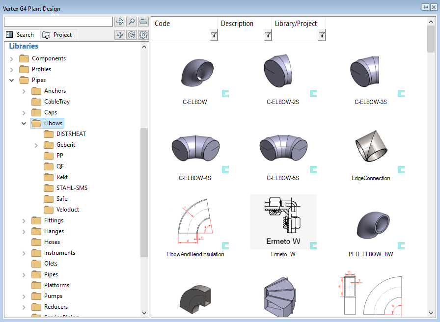
How to use your own pipe components
You can find your own pipe components from the folder Pipes > Own in the browser.
In case you have created subfolders for your pipe components you will find them from the folder Own as subfolders.
Please update the Browser if you don't see your pipe components straight away.
While you are designing your pipe system you can find your pipe components from the folder Own.
The standard pipe components which are coming with the program are located in the folder Standard.
Please do the following steps if you face problems with your pipe component in the isometric drawing:
Select the problematic pipe component from the assembly > Sheet Piping > Item data.
This will open the window COMPONENT DATA.
The lower right corner contains the button Help > Click that > The guide contains a topic "Requirements of isometric drawing" > Make the necessary corrections.
Please activate the full-screen mode to see the video properly. Exit the full-screen mode by clicking the Esc button.
How to create new pipe class
You can easily create a new pipe class to the pipe class database (d_PIPECLASS).
Activate the sheet System > Pipe classification > Pipeclasses > The window Classes opens.
Select one row from the database view > Right mouse button > Add row before/after.
Define the new pipe class by filling the fields:
Class - The code of the pipe class which is visible while you are routing pipelines and which you gove to the pipe components in the pipe component database.
Description - The clear and informative description of the pipe class.
Standard - The standard of the pipe class.
PN - The nominal pressure of the pipe class.
Conn. tol. - Fill value to this field if you want to use a class-specific connection tolarance instead of the general tolerance.
Angletol. - Fill value to this field if you want to use a class-specific angle tolarance instead of the general tolerance.
Main Group: Each pipe class belongs to one main group. There are four main groups: "1 pipe component", "2 duct component", "3 cable ladder component" and "4 platform or stair component".
You can define class-specific connection components to each pipe class at the bottom of the view. The data is saved to the database (d_PIPECLASSMAT).
Select one field from the connection component fields > Right mouse button > Add row before/after > This will activate these seven fields.
Type or select from the drop-down menu Dimension standard and Material for bolts, nuts, and washer. Define also Surface treatment. The connection components of the flange connection will receive the data according to these specifications.
Save your changes to the database of the pipe classes by closing the window from the button OK. The class is now ready for usage.
Please activate the full-screen mode to see the video properly. Exit the full-screen mode by clicking the Esc button.
Check out also Advanced.