
Elbow
Basics
This guide tells you how to get the modeled or converted elbow component to work automatically during pipe routing.
Define elbow as elbow
Open the elbow's model > Right Mouse Button> Properties.
The Part Properties window opens> Pipe comp. info.
The Pipe component info window opens > Select the radio button Elbow > Enable the check-box Fixed.
The dimensions of the component do not change when you edit the assembly if the model is Fixed.
Please activate the full-screen mode to see the video properly. Exit the full-screen mode by clicking the Esc button.
Database data
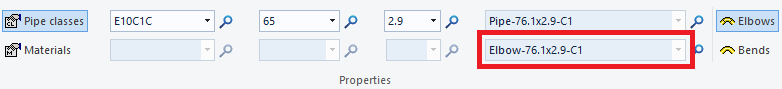
Specify the appropriate Class and Type for the pipe component elbow. The Class must be from the group Elbows and Bends.
Fill in the other details on Pages 1-3 as usual.
You must specify a Radius for the elbow to position it correctly on the pipeline during pipe routing.
See the following steps for further details on the radius definition.
On Page 4, you can also specify values for angle behavior (Angle min. and Angle max.).
If the angle of the elbow is constant, fill the same value in the fields Angle min. and max., for example, 90.
If the maximum angle of the elbow is a limiting factor, only specify a value in the Angle max. field.
Please activate the full-screen mode to see the video properly. Exit the full-screen mode by clicking the Esc button.
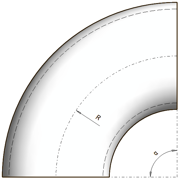
How to define radius - Normal elbow
For a normal elbow, the Radius (R) is the same as the radius of the centerline of the elbow.
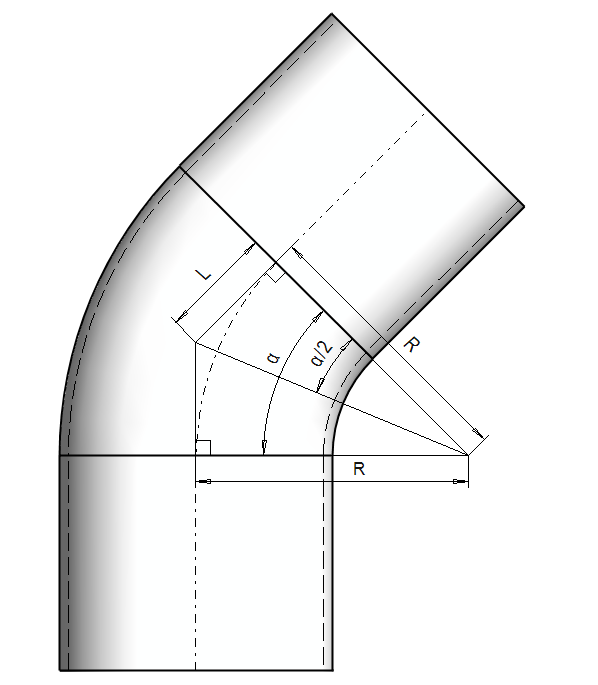
How to define radius - Elbow with straight segments
In these cases, the Radius (R) of the elbow is calculated by the following formula:
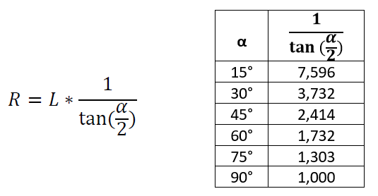
When defining the radius, the dimension L is determined from the curved portion of the centerline. The straight sections of the centerline are not included in the calculation.
The table above shows the pre-calculated values for the most typical degrees.
Enter the value in the database to two decimal places when it is not an even number.
Valve with handle
Handle of valve
Insert the pipe component centerline to your modeled or converted model as usual.
Insert also a line to mark the direction of the valve handle.
The length of this line is not important. It's recommended to fix the line to other geometry with the constraints if your model is variable.
Add the pipe handles (Insertion points) as usual. The line which marks the valve handle does not need the pipe handle.
Please activate the full-screen mode to see the video properly. Exit the full-screen mode by clicking the Esc button.
Save the valve to the pipe component library as usual.
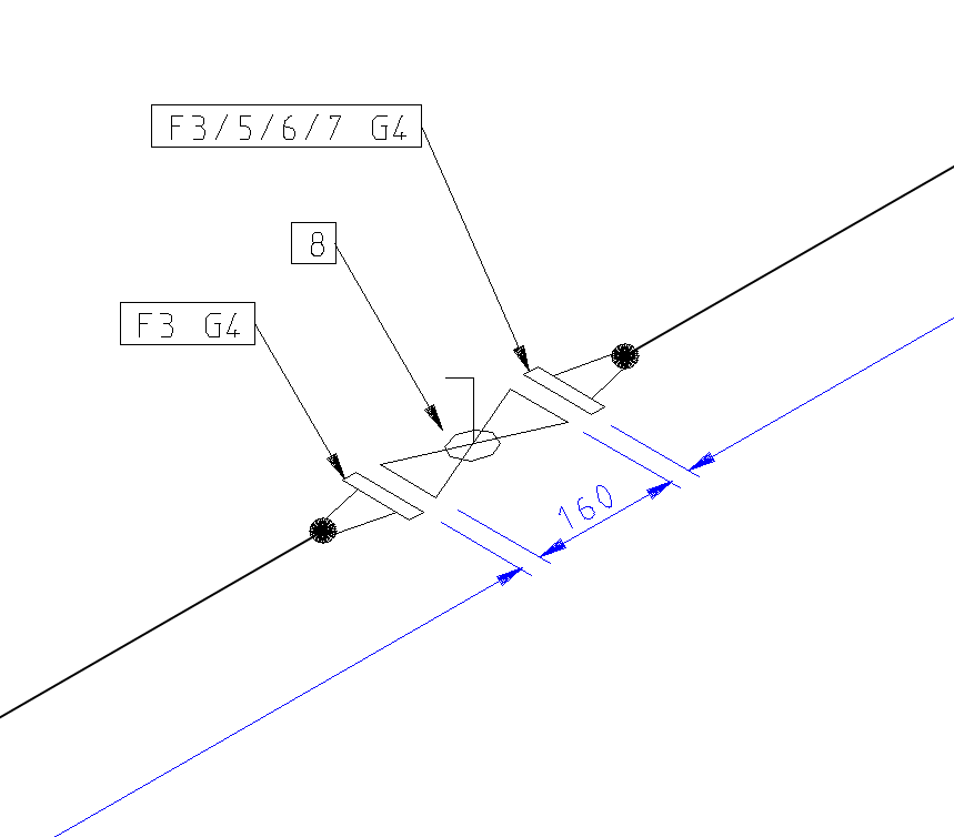
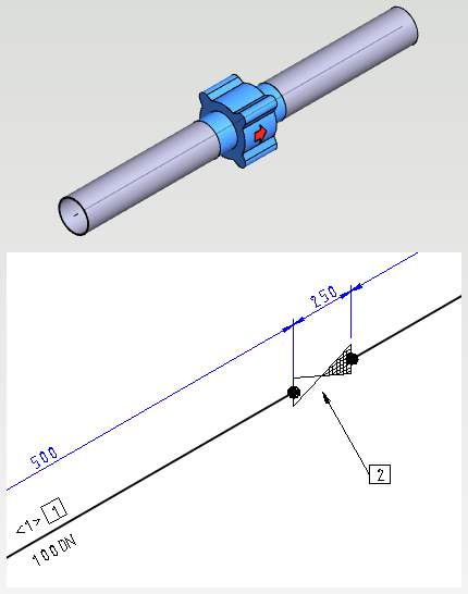
Isometric drawing
The valve with the handle is visible as shown in the picture below.
Check valve (Non-return valve)
If you want to determine the flow direction of the check valve to the isometric drawing, give the valve the Class CKxx in the pipe component database.
The first insertion point (P1 in the figure) is the first in the flow direction and the second insertion point (P2 in the picture) is the latter in the flow direction.
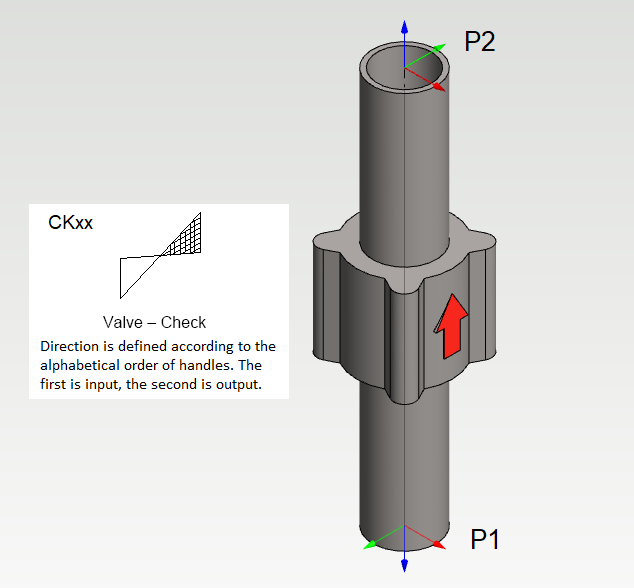
Now the relative position of the check valve's handles in alphabetical order determines in which position the check valve symbol is drawn on the isometric drawing.
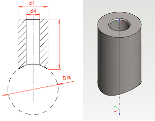
Olet
The various olets and branched to be welded to the side of the pipe require a few special arrangements to make them work properly in the pipeline design and the isometry drawings.
Model the pipe component for its dimensions. Place the other end of the pipe centerline where the centerline of the mainline is. The dimension drawing and model below are the pipe component olet_therm_TK1.
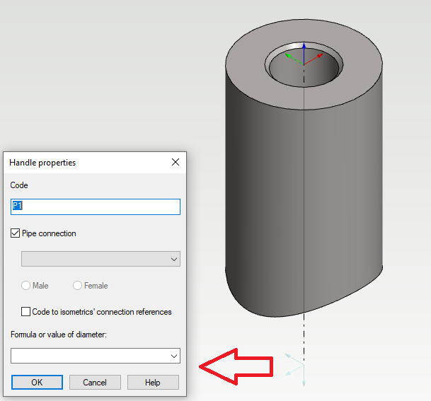
Place the pipe handles (Insertion points) normally with the difference that leave the Formula or value of diameter value blank in the Handle properties associated with the mainline. See the example below.
If the component needs to be positioned on the model in a specific orientation, such as the temperature probe used as an example, turn the green arrow on the pipe handle parallel to the pipe centerline. You can rotate the directions of the pipe handle axes with the Move function while you are defining the insertion points.
Please activate the full-screen mode to see the video properly. Exit the full-screen mode by clicking the Esc button.
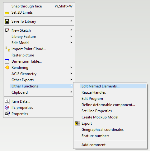
You can also modify the direction of the handle axes afterward: Open the pipe components model > Working window > Right Mouse Button > Other Functions > Edit Named Elements...
Pipe assembly
Type and Class
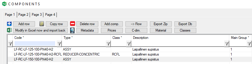
The pipe assembly, which is saved to the pipe component library, receives a value ASSY for the Type and the field Class is empty as a default.
The user can define a different class for the pipe assembly, for example, RCFL.
This change has an impact on how the pipe assembly behaves in the isometric drawing and its parts list.
Assembly's Type is ASSY
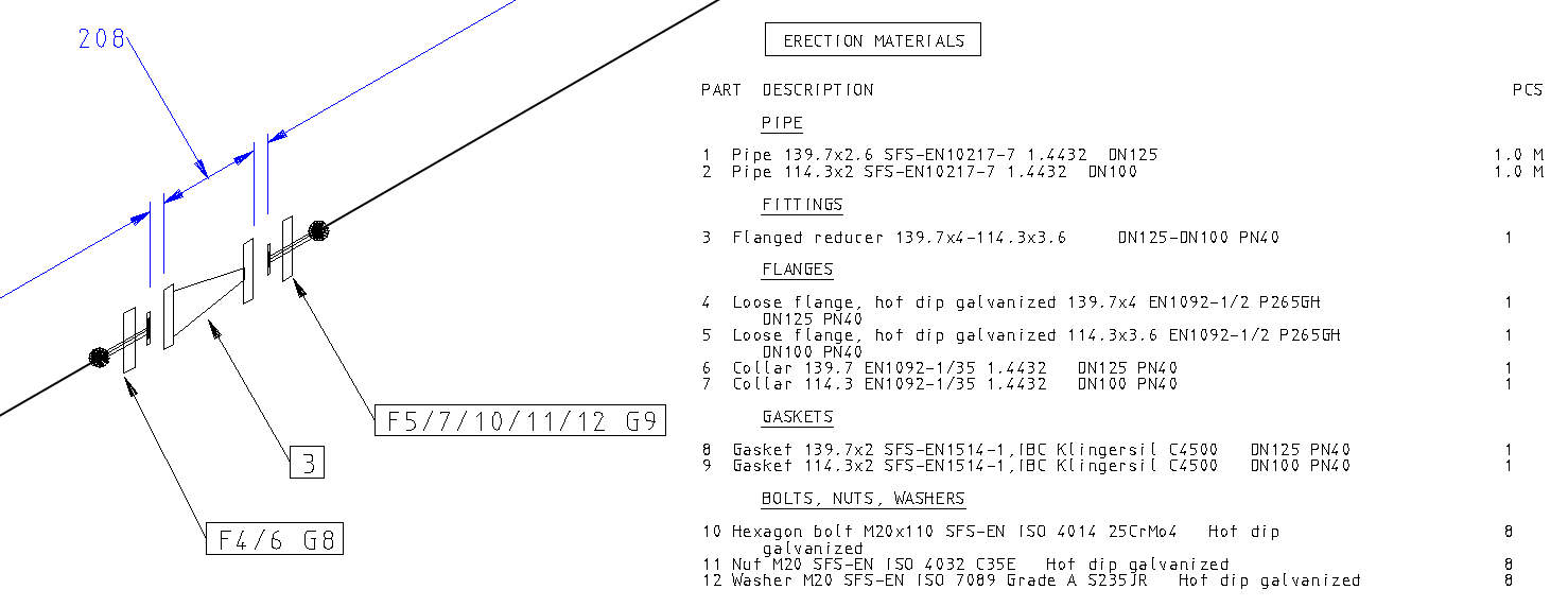
Isometric drawing
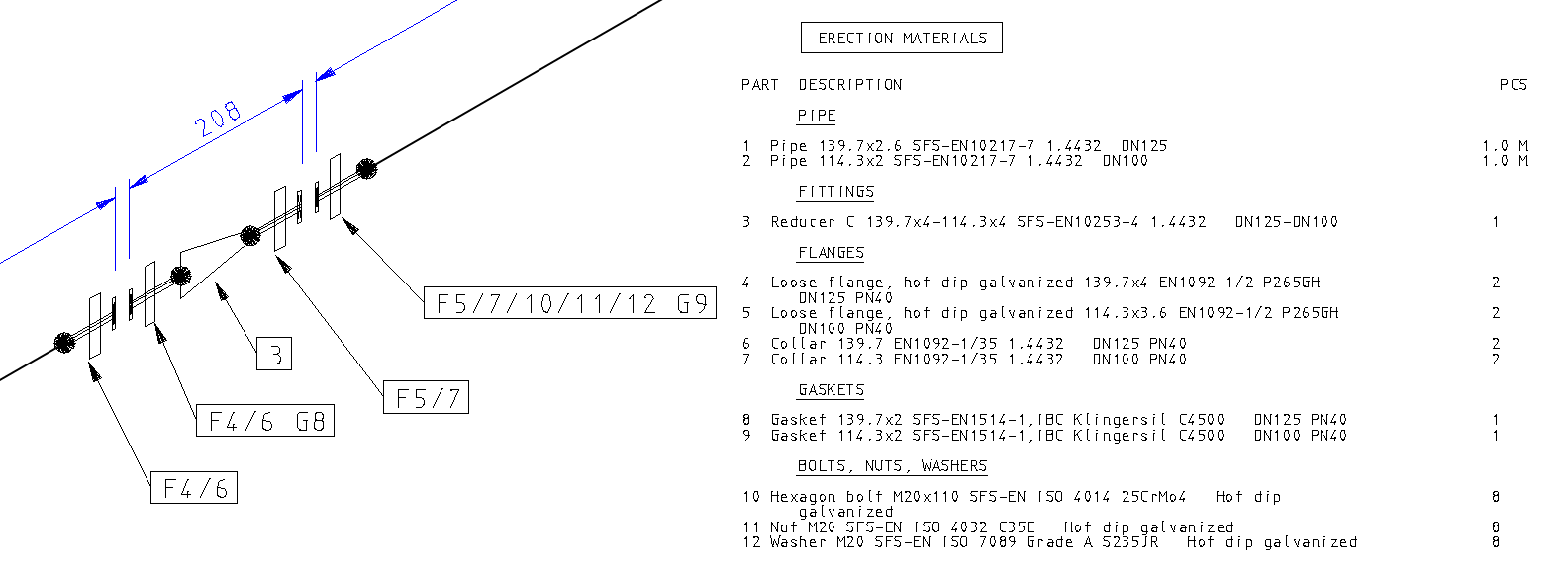
The pipe assembly behaves in the isometric drawing as any other assembly.
The isometric symbols appear to the drawing for each component in the pipe assembly separately.
The parts list contains each component of the pipe assembly separately.
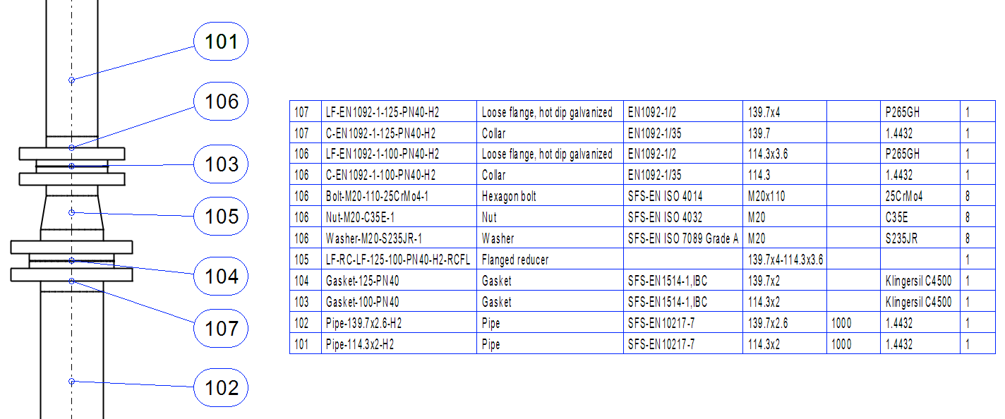
Normal drawing and Excel listing
The type and class of the pipe assembly influence also to the pipe assembly's behavior in the parts list of the normal drawing and the Excel listings.
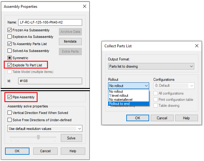
When you save the pipe assembly to the library, you define that the assembly is Pipe Assembly in the Assembly Properties window.
You can also define are the part list showing only the mother row or te parts of the pipe assembly in the Assembly Properties window:
-
Explode To Part List disabled: The parts list shows only the mother row.
-
Explode To Part List enabled: The parts list shows only the parts.
There is an option Rollout to end when you collect the parts list. This allows you to collect the pipe assembly's parts to the parts list even the Explode To Part List is disabled.
Assembly's Class is SKEY class
Isometric drawing
Putkikokoonpano käyttäytyy isometrissä kuten mikä tahansa putkikomponentti.
Isometrisymboli piirretään SKEY-luokitteen mukaisesti.
Isometrin osaluettelossa listataan vain putkikokoonpanon ns. äitirivi.
Normal drawing and Excel listing
The type and class of the pipe assembly influence also to the pipe assembly's behavior in the parts list of the normal drawing and the Excel listings.
When you save the pipe assembly to the library, you define that the assembly is Pipe Assembly in the Assembly Properties window.
The window Assembly Properties contains the check-box Explode To Part List. Disable it if you want your pipe assembly yo behave in the same way in the parts list of normal drawing as it does in the isometric's parts list. The parts list will show only the mother row (part 105). The option Rollout to end does not have an impact on the parts list in this case.
Bolt surfaces
General
It's possible to define the so-called bolt surface to flanges and flanged equipment.
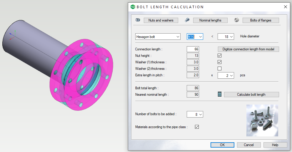
The program can insert semi-automatically required connection components to a flange pair with the help of the bolt surfaces. The connection components are not visible in the assembly. The program adds them to one of the flanges in the pair as un-modeled items.
The materials of the connection components are determined according to the specification for the pipe class. You can find more detailed instructions here: How to create new pipe class.
The number of connection components and the physical dimensions is determined by the databases Bolts of flanges (d_FLANGES), Bolt nominal lengths (d_BOLTLEN), and Bolts, washers, pitch (d_NUTSIZE).
Note! For equipment coming between flanges, such as a non-return and butterfly valve, you do not need to specify bolt surfaces. In these cases, the connection length is calculated based on the distance between the bolt surfaces of the mating flanges.
How to define the bolt surface
You can add a bolt surface to both the self-modeled and loaded pipe components. You can add it when making a pipe component or afterward.
Select the bolt surface from the model > Right mouse button > Properties > Type Name >
-
If the pipe component has one bolt surface, then the surface name is BOLTS
-
If the pipe component has two or more bolt surfaces, the names of the surfaces are BOLTS1, BOLTS2...
Close the window Name? by clicking the OK button.
Save the model.
How to edit the bolt surfaces
If necessary, you can edit or delete surfaces as follows:
Open the model > Right mouse button in the working window> Other Functions > Edit Named Elements...
Select the radio button Surfaces and you will find the bolt surfaces from the list. Do the necessary changes.
Please activate the full-screen mode to see the video properly. Exit the full-screen mode by clicking the Esc button.