Vertex FEA documentation and examples can be found in this page. The functionality is available in Vertex G4, G4 Plant and BD software. Design Codes such as AS/NZS 4600:2005 Cold-formed steel structures can be included to Vertex BD software.
Vertex FEA software options:
|
|
G4 |
G4 Plant |
BD |
|---|---|---|---|
|
FEA for Solids and Assemblies - VXO-464 |
x |
x |
|
|
FEA for Beams and Frames - VXO-465 |
x |
x |
x |
|
Design Codes - VXO-466 |
|
|
x |
Vertex FEA – versatile structural analysis for parts, assemblies and frames
Vertex FEA creates linear static analyses for parts, assemblies and frames. The result of the analysis returns stresses, deformation and support reactions. FEA analysis stores loads and analysis parameters to the Vertex model and it can be re-analysed easily after geometrical changes. The analysis is very fast and FEA meshing can be changed easily by the user. Analysis reports can be created easily as well.
Strength analysis can be created fast and easily in Vertex
Vertex FEA modules are integrated in the heart of the Vertex software and are available for several products. New analysis studies can be created easily to referred geometry model and performed as linear statics analysis. Geometrical model supports multiple studies, so different kind of analysis situations can be modeled and modified easily.
Part analysis
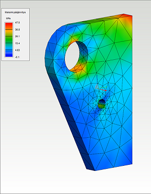
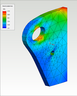
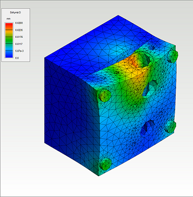
Loads and boundary conditions can be set individually to the surfaces of the part. Stresses and deflections are visually observed in the model when the analysis is done.
Deflection of the part.
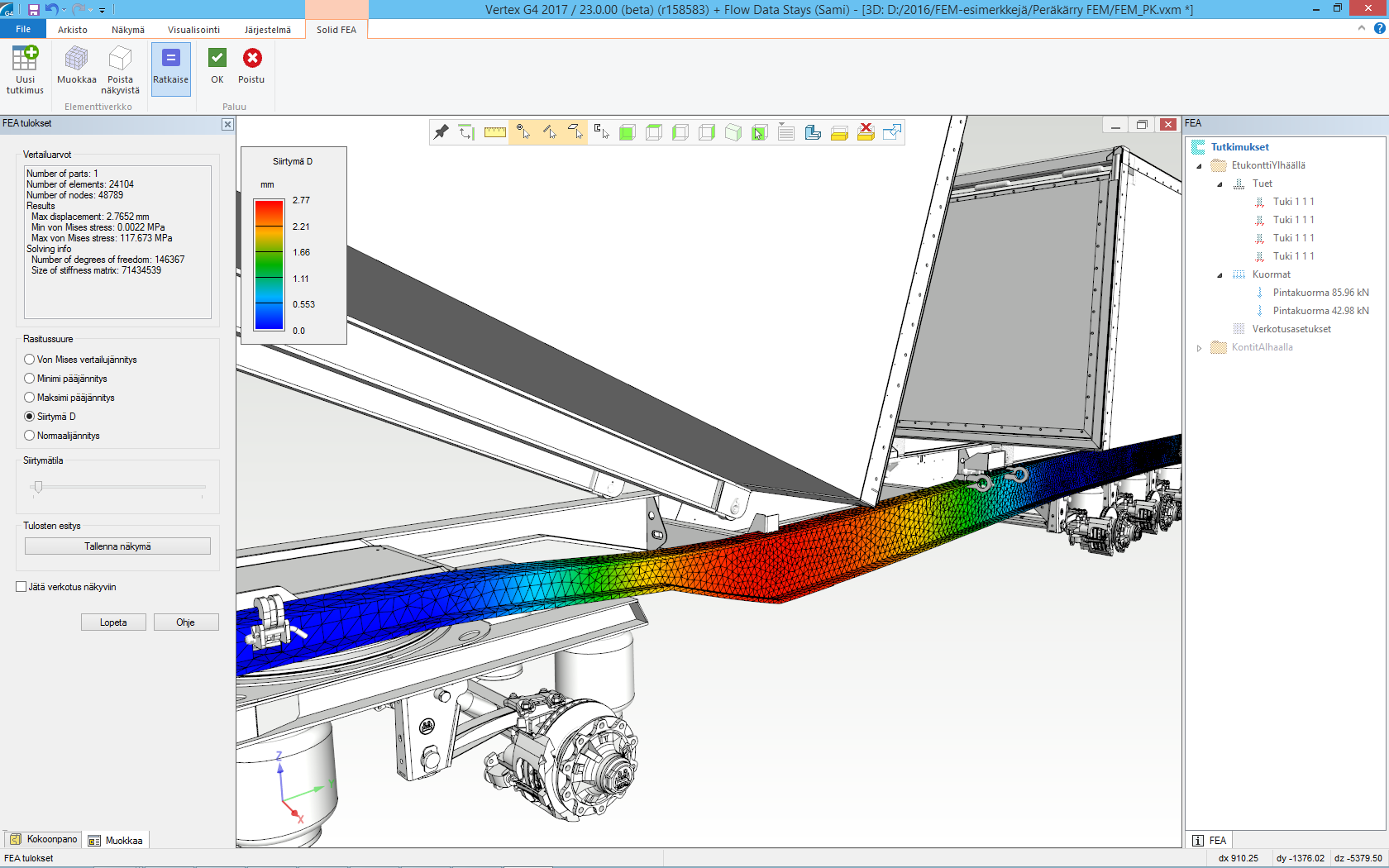
Assembly analysis
Parts of the assembly can be connected together with contacts or they can be considered as one welded part. Contact assemblies are solved iteratively by calculating the analysis model several times. Boundary conditions of the assembly are updated along the iteration while surface pressures are observed after each round.
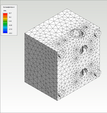
Mesh is created for the assembly geometry.
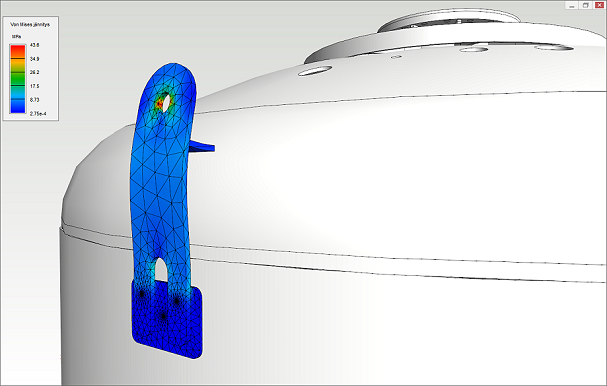
The lid of the block is attached with bolts to the block. The lid disengages from the block when pressure between parts increases.
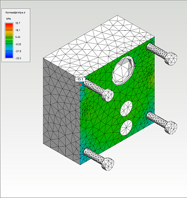
Surface pressures of the contact surfaces can be studied.
Create more accurate analysis by refining the mesh in the critical areas
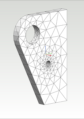
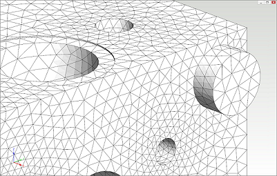
Powerful meshing tool of FEA for Parts and Assemblies creates meshes using 4 or 10 noded tetrahedron elements. User can modify the mesh by refining it in the critical places to increase the accuracy of the analysis.
Geometry meshed with 4 noded tetrahedron elements.
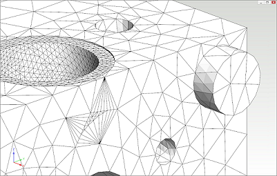
Geometry meshed with 10 noded tetrahedron elements.

Mesh is refined near the hole.
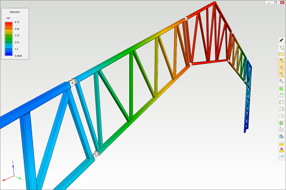
Profile structures
Profile structures can be analysed with FEA for Beams and Frames functionality. Analysis model is created from a geometric profile model and it supports widely different kinds of loads i.e. point, line and thermal loads. Results of the analysis shows visually in the model the common stress conditions such as deflection, bending moment, shear force and normal stress.
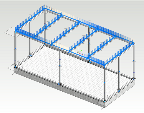
Line loads are applied to the profile structure.
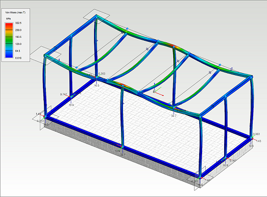
Von Mises -stresses are visualized in the surfaces of the 3d model parts.
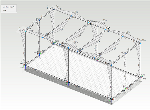
Typical stress plots drawn into the model.
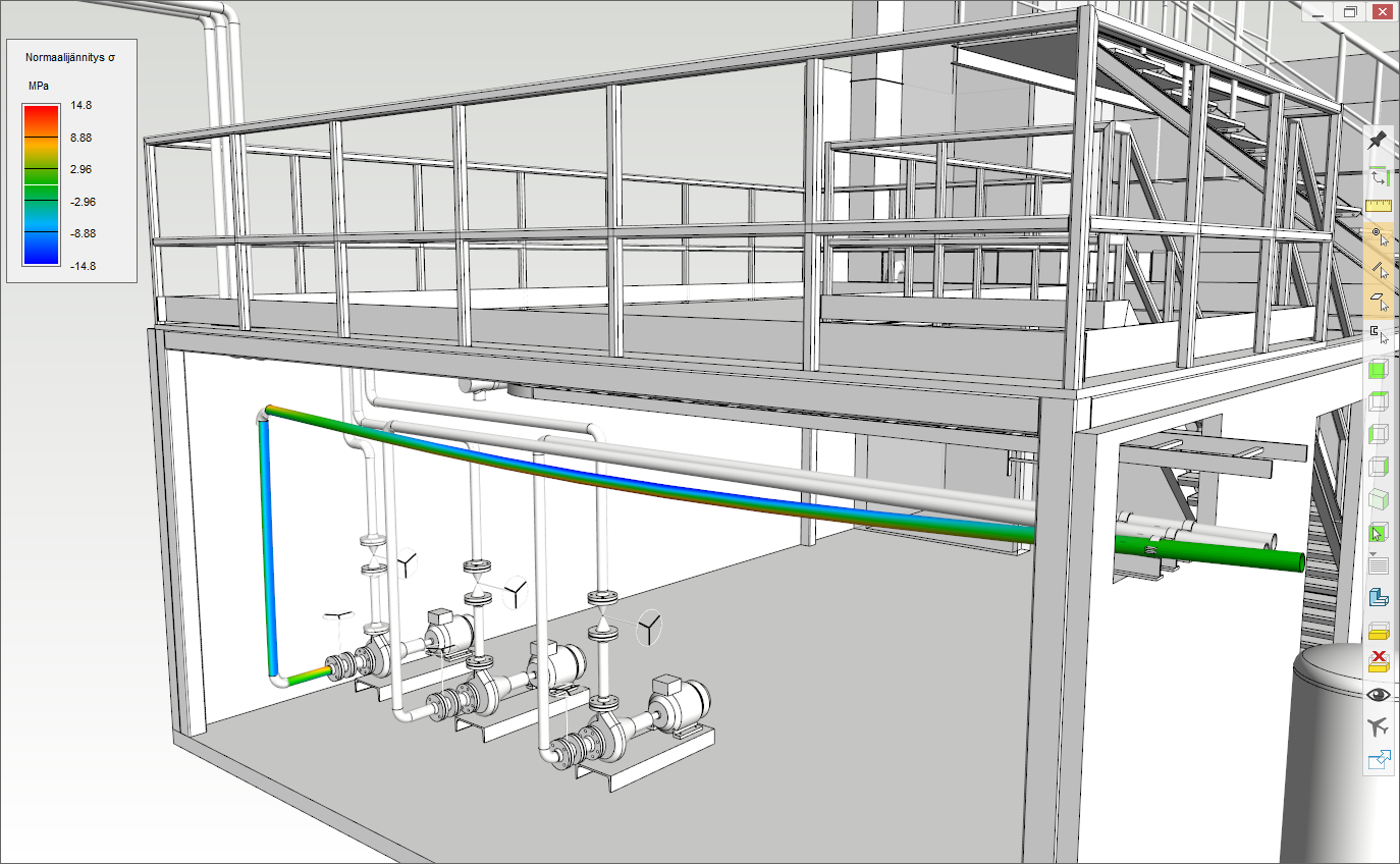
Pipelines
Pipelines can be analysed with external loads, the content of a pipe and thermal stresses. The analysis solves pipeline stresses, supports, deflections and support reactions. Even the pipeline is analyzed first with another software function. Prechecking reduces mistakes and speeds up the design process.