Different designs
Modeling Techniques
With Vertex G4, like all 3D mech.eng. softwares, you can make models with many different ways. All techniques have their good and not-so-good properties.
Practically all technical products are assemblies, and there are two basic ways to design the models:
"Bottom Up"
"Top Down"
Dramatic Differences
Both ways can produce a model, which look exactly the same when you view the model, the drawing and bill of material, but time needed for changes to the models may be anything between a few seconds and clicks to many hours of work. A good advice is to have rules and principles which should be followed by all designers in the product development team.
Bottom Up
- When: Making assemblies from standard parts, like Lego- bricks
- How: All parts are standardized, install and mate then to each other.
- Parts are located by their constraints to other parts.
Good things:
- Very fast way to make an assembly.
- As you use only standard parts, no unnecessary new items are generated which affects directly to inventory value and keeps it low.
Not-so-good things:
- Any changes in the assembly normally requires re-positioning other parts.
- Plenty of constraints in assembly, which makes it more difficult to handle.
- if you have to change the assembly overall dimensions, you have to change each part individually which takes time and may cause errors.
Top Down
Design for Assembly
- When: When you have to deliver products with customized dimensions. The construction may be the same, but each customer requires different dimensions.Or when you are designing totally new constructions and do not know yet, whati kind of parts will be needed (= behavioral modeling")..
- How: Parts are modeled in the assembly by using skeleton- or jig- type parts. Skeletons define parts and also their relations and positions.
Good things:
- Reduced amount of constraints in the assembly. Most constraints are in the skeleton part sketches, which normally are planar, and thus easy to handle.
- Removing or changing parts in the assembly does not necessary affect to other parts positions.
- Assembly overall dimension change is carried out by just changing the skeleton part dimensions and solving other parts using one command.
Not-so-good things:
- You have to make preliminary work before getting any visual result.
- All parts with different dimensions require new items and will increase the inventory value.
Cases
See a few cases using "Top Down" philosophy
Profile Structures
Always make first a local part named "Jig" or "Skeleton", mostly consisting of guide lines. Set part properties "Do no collect to parts list" and "Do not show in drawings". To change assembly dimensions just edit the skeleton part and change the dimensions. Then return back to assembly and click "Solve".
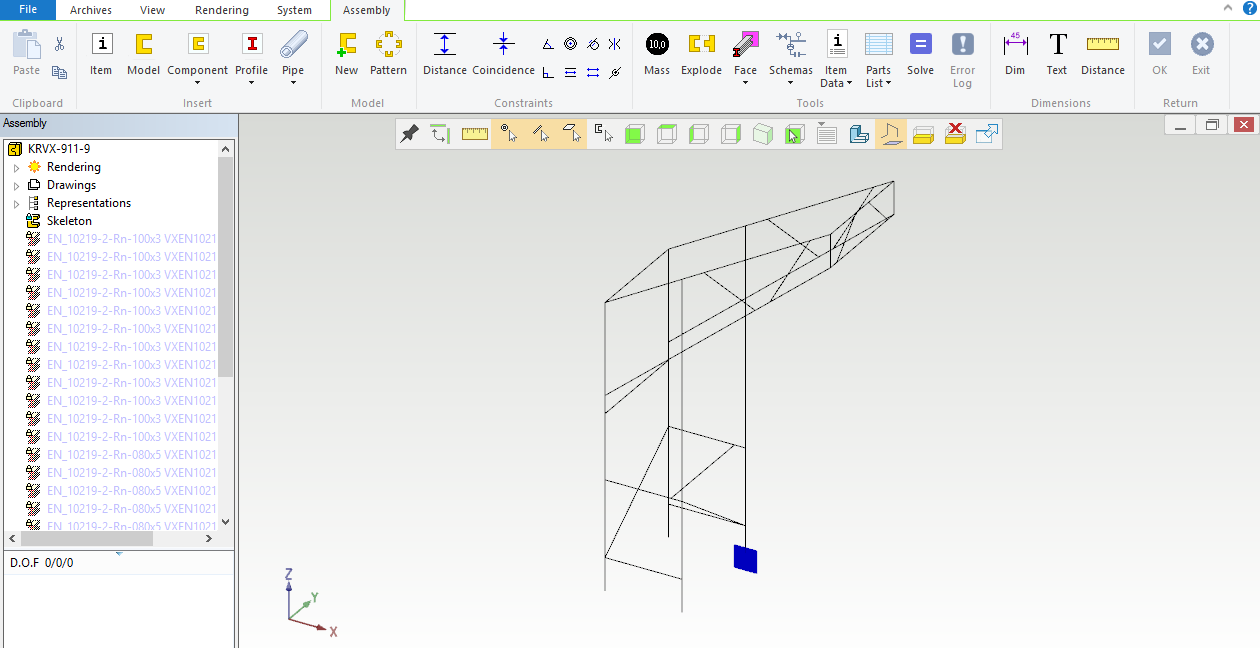
Picture 1: Profile assembly with only the skeleton part visible. Skeleton consists of sketches which are positioned on base planes and other lines.
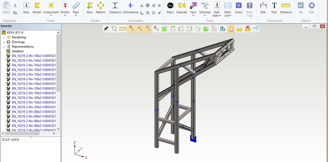
Picture 2: The same assembly with all parts visible.
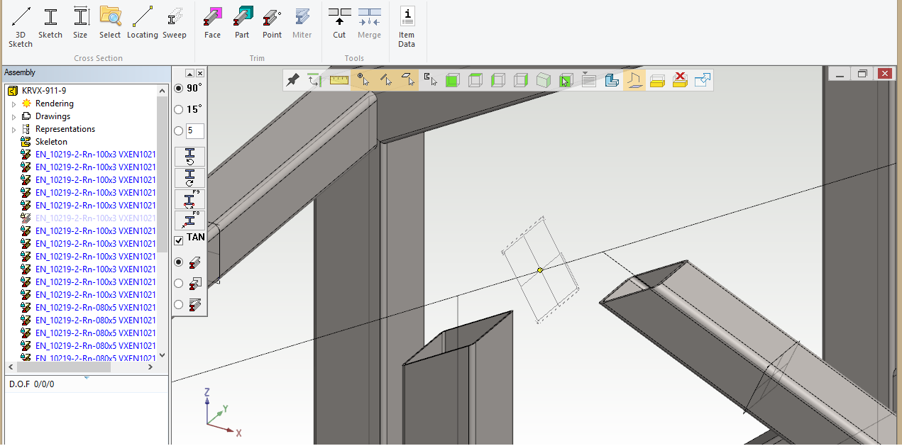
Picture 3: Insert profiles by ckicking the profile cross section on line, and the profile part is swept along the line. You can adjust the profile location from the buttons on the left top of the geometry area.
By default all profiles are local parts and their item label, description and length will be printed to parts lists. You can also save the profile part to individual (linked) file. This part will still follow the skeleton, but it has now an own label, model file and production drawing.
See a video showing how to make profile models:
In Vertex G4 there is a large library of standard profiles. You can make your own cross sections bu sketching the geometry and saving them to your own library.
Box-type Sheet Metal Constructions
Again, start with a skeleton part. For box- shaped constructions the skeleton often is a solid model representing the box volume. Actual sheet metal parts are then easily created by copying faces from the skeleton model and giving them sheet thicknesses. After creating the initial sheet geometry you can add other features like holes, flanges etc. Parts will always fit to each other and to change overall dimensions of your constructions just edit the skeleton part, return back to the assembly and click "Solve".
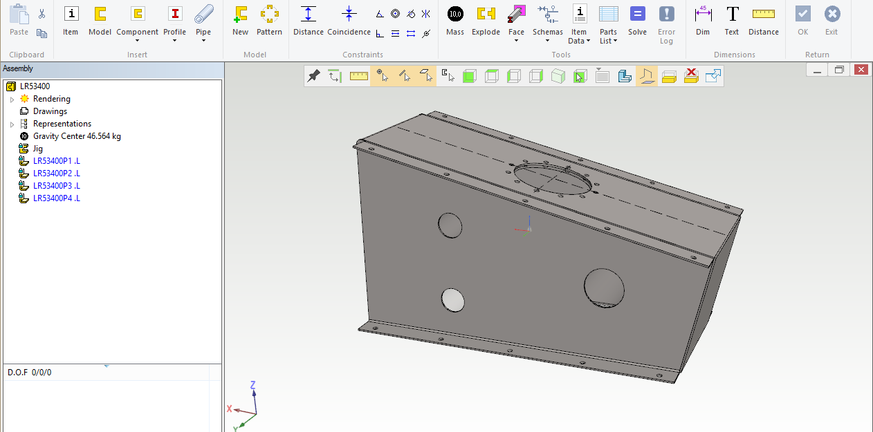
Picture 1: This is our construction, a gearbox housing. Side plate holes must be concentric and of same diameter on both sides. In the top plate there is a service hatch and a hole pattern to fasten the flange.
We begin our design with a skeleton part.
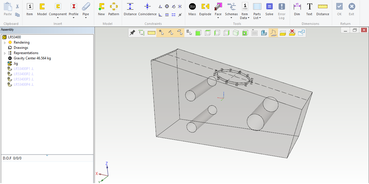
Picture 2: Skeleton part which in this case is a solid volume model. Side holes are cutout extrusions thru the entire part and top hole is 12 mm deep, although the depth here is not important.
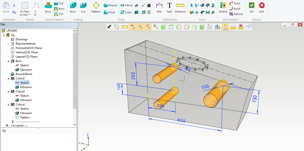
Picture 3: An example of the skeleton part sketch defining the side holes.
Create all new sheet metal parts as follows: Create a new part into the assembly. Right-click "Copy surfaces"- select, and give sheet thickness and offset direction. You can also make bends by adding rounds to the skeleton and copy faces with tangency option.
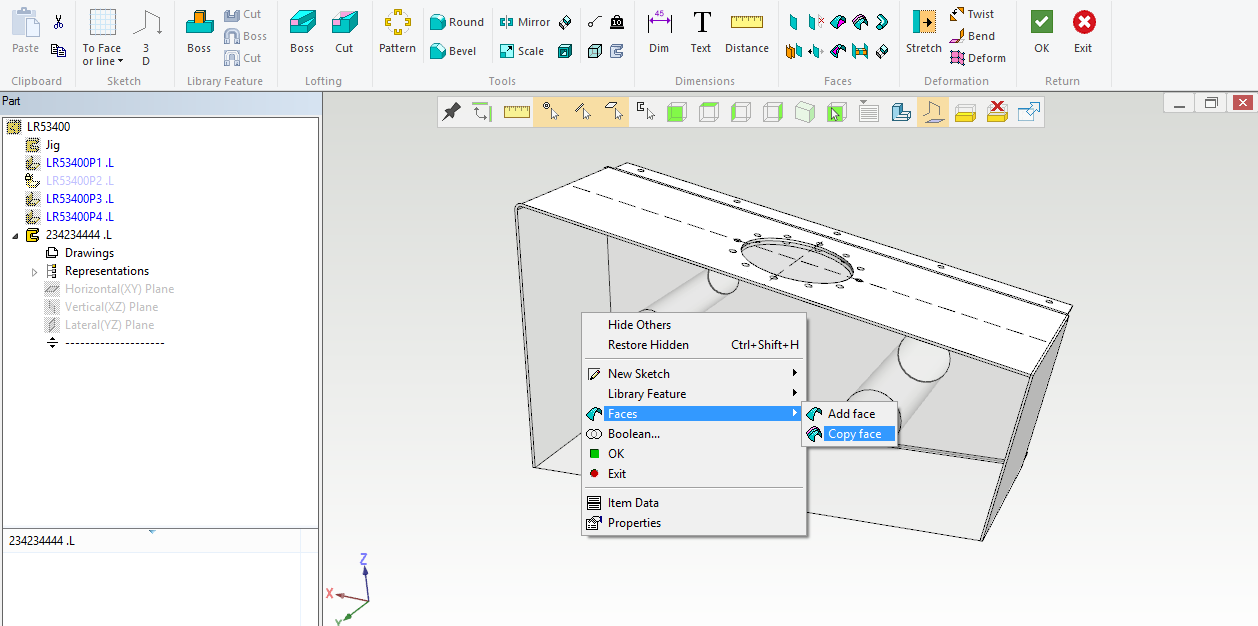
Kuva 4: New part with the first feature is copied surface from the skeleton. Tangency option can be selected from the top left corner of the geometry area.
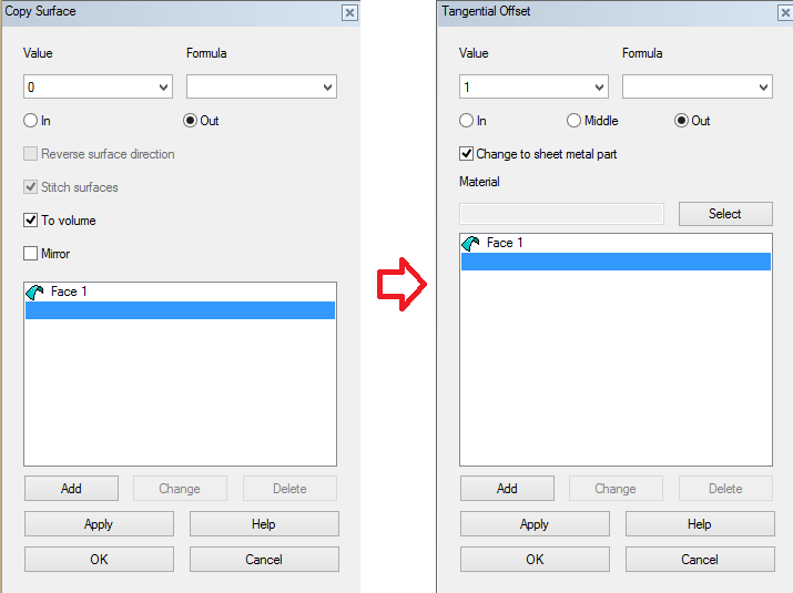
Kuva 5: Select "Create volume model" after selecting the surfaces. This will create a sheet metal part automatically.
Changing assembly dimensions can be made as follows:
a. Edit skeleton part - return to assembly - click "Solve".
b. If your skeleton part has variable labels (formulae) in its dimensions and features, just right-click and select "Dimension Table" - "Variables Only" in the main assembly - give new values - OK.
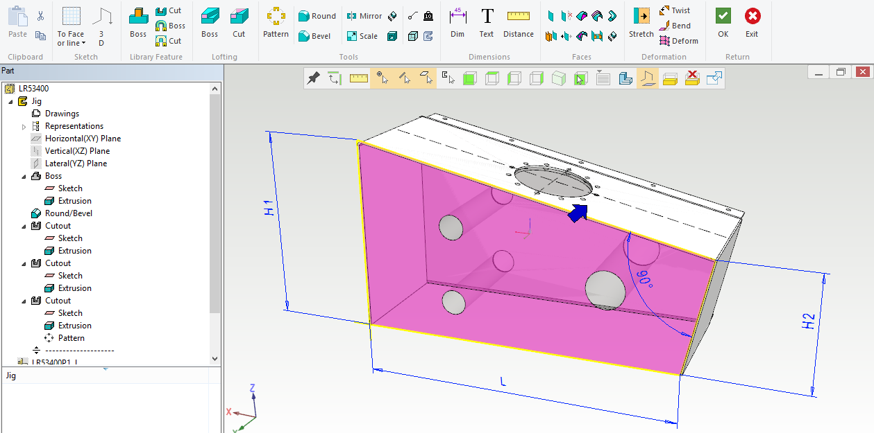
Picture 6: Skeleton part with formulae in a sketch.
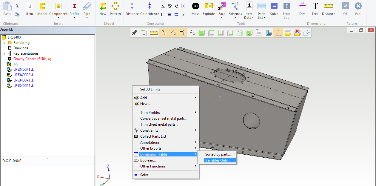
Picture 7: Table of Dimensions.
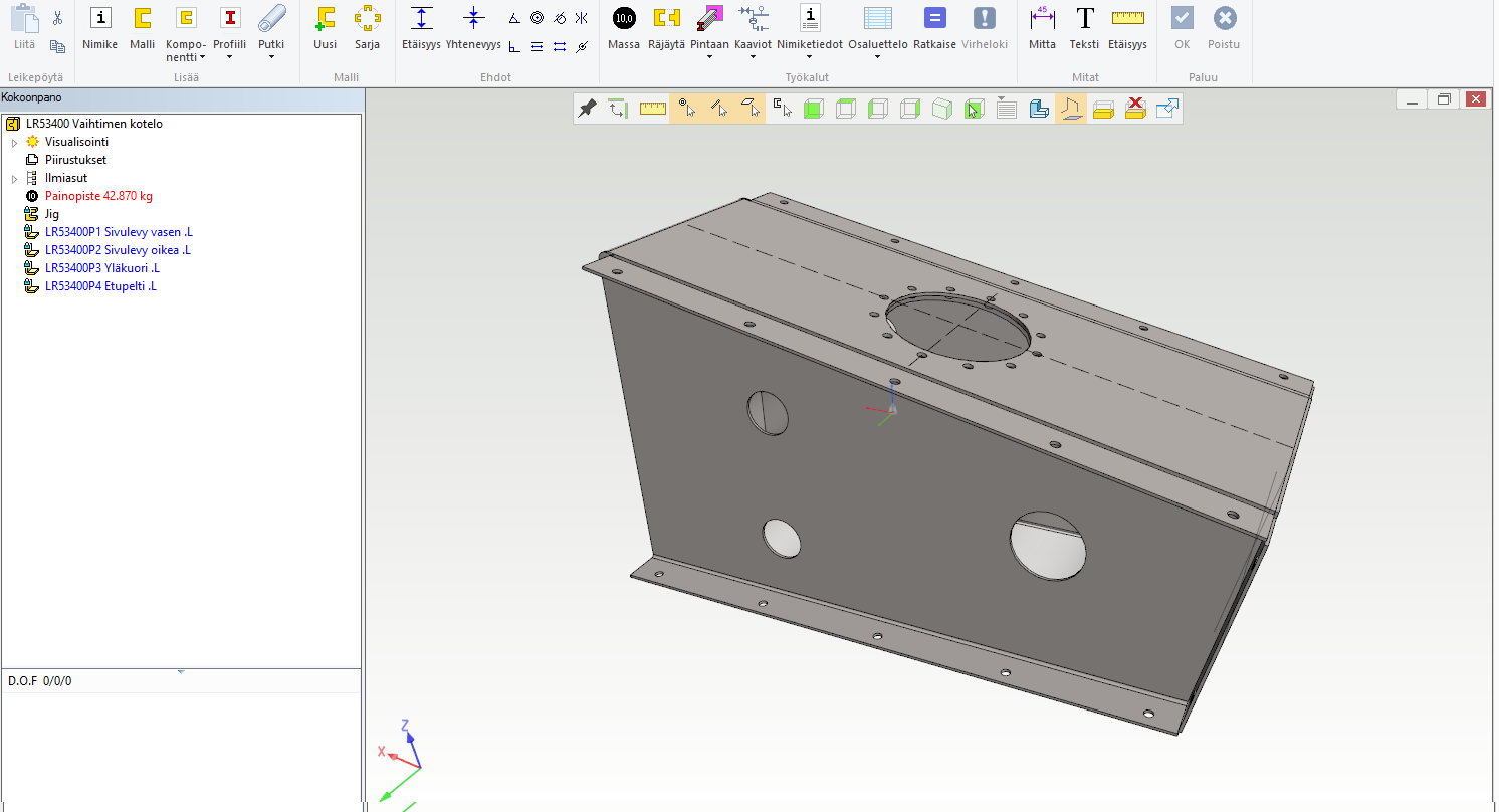
Picture 8: Box bottom dimension changed from 850 mm to 920 mm. All parts have been changed automatically. Note that there are no constraints in the assembly as all parts follow the skeleton.
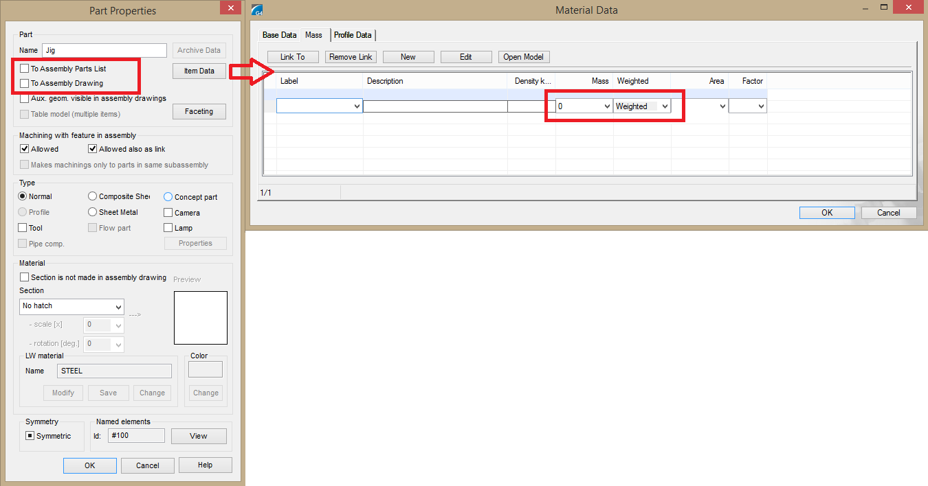
Picture 9: Skeleton Properties.
Note that "Solve" overwrites all linked parts which have an external references to the skeleton.
Pressure Vessels and Pipe Connectors
These types of products use skeletons with both solid geometry and guide lines. The solid geometry represents the pressure vessel shape. Additionally you make guide lines for the leg construction.
All joints are positioned by making guide lines.
This results to a skeleton which resembles a "Christmas Tree" with many lines to different directions. But this makes it very easy to control the pressure vessel dimension sand joint positions.
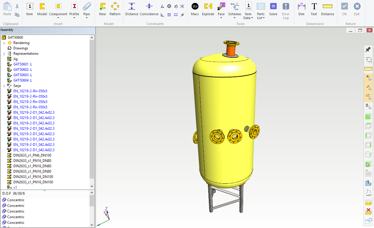
Picture 1: Our construction: a vertical pressure vessel standing on profile legs.
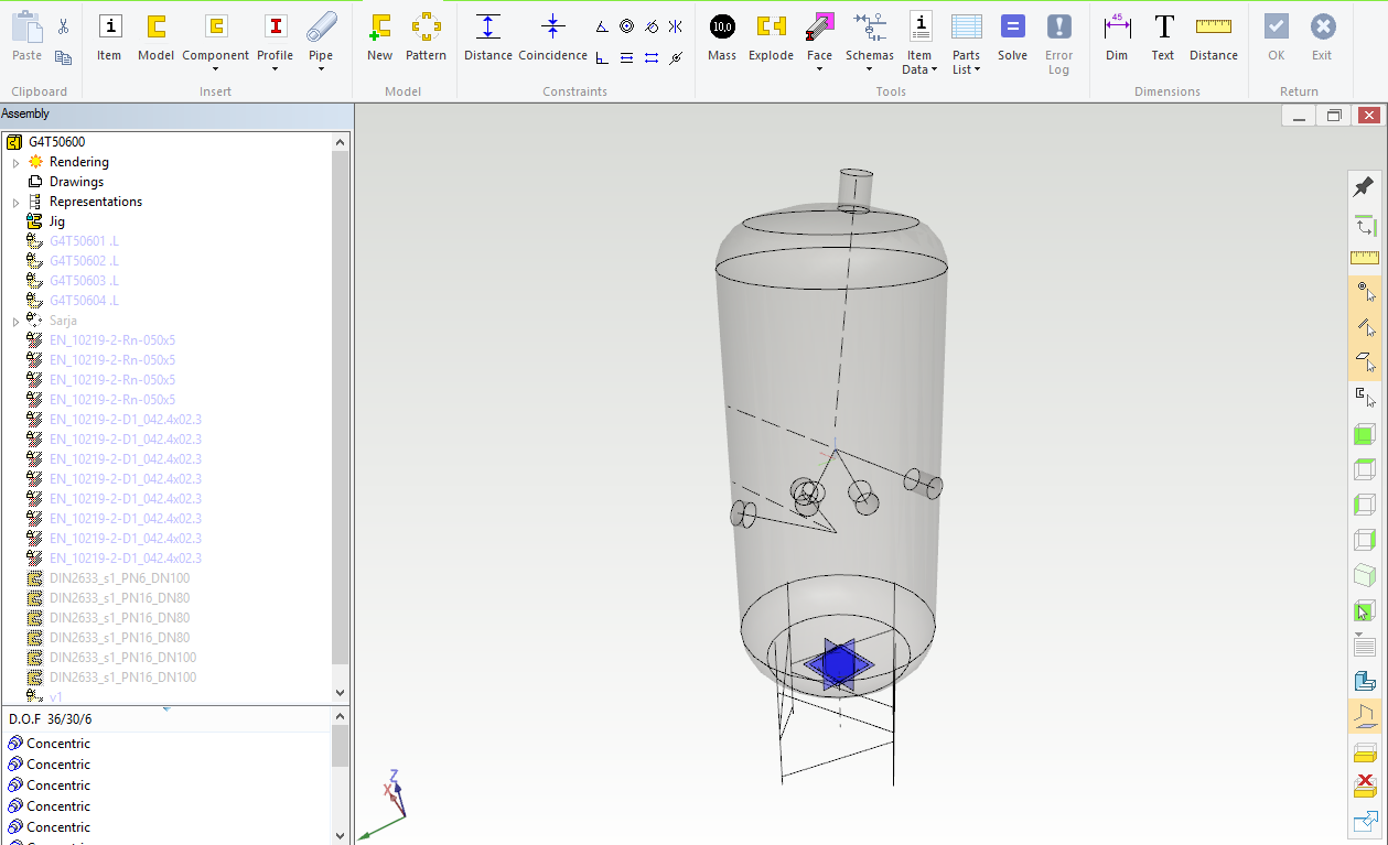
Picture 2: And our construction begins here: Skeleton with all necessary geometries.
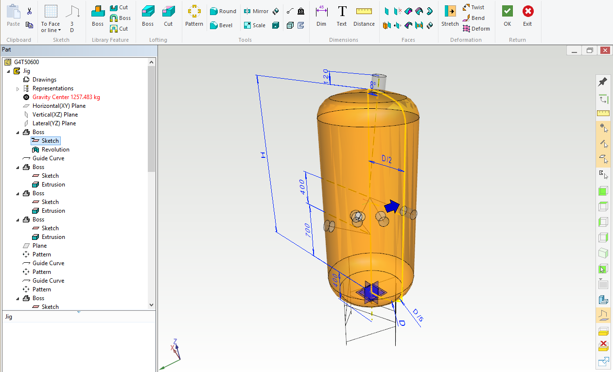
Picture 3: Pressure vessel basic shape and height positions for the joints.
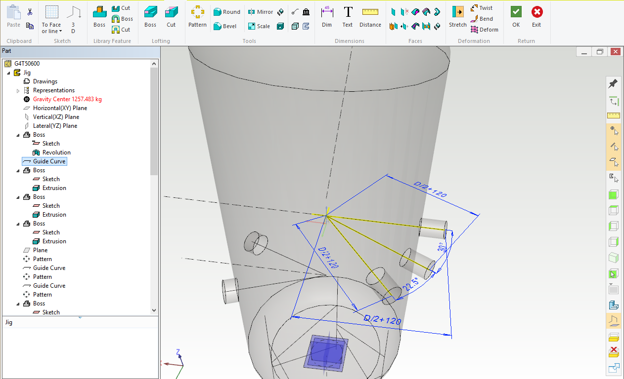
Picture 4: Joints on level 700 mm positions (angles) to each other. Joints are made by making a sketch to the line endpoint and extruding the circular shape to the pressure vessel cylinder.
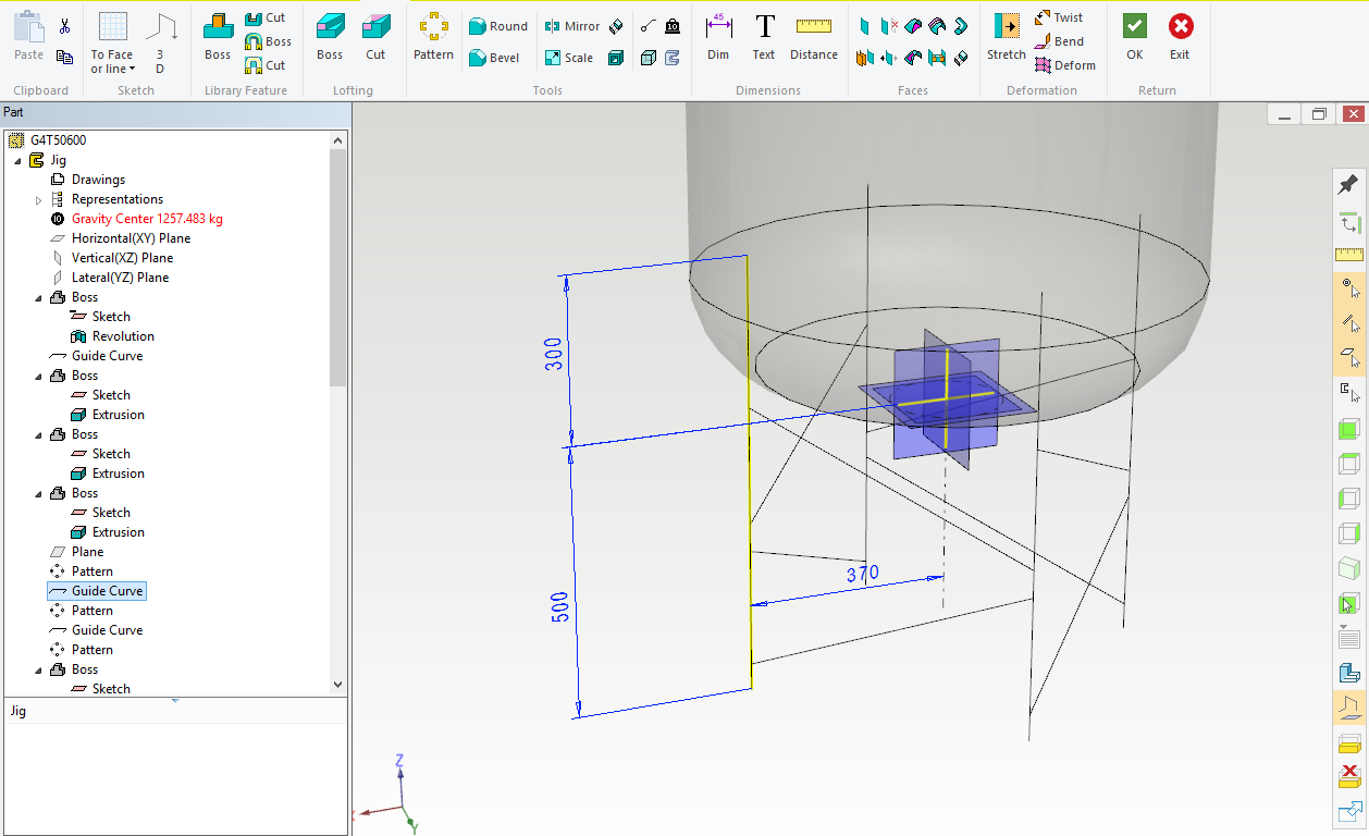
Picture 5: Legs are swept as profiles along these guide lines.
Pressure vessel parts can be made like in box-shaped constructions, by copying surfaces from the skeleton and giving offset (= sheet thickness).
You can use this kind of a skeleton also for calculating the pressure vessel volume, which often is an important design criteria.
Modeling Parts
Skeletons can be used for parts modeling, too. Next example shows a bracket, with dimensions drawn to the skeleton part. Now you can design the actual construction with many different ways.
You can also make skeleton geometry into the part model. First make the guide curves representing main operational properties, like base width, hole position and diameter. After this the "real" geometry can be made using the skeleton geometry. When using this part in an assembly, you can constrain the part using skeleton geometry. Now you can change all "real" geometry without losing the constraints. This gives you freedom for your part geometry or changes to the part topology.
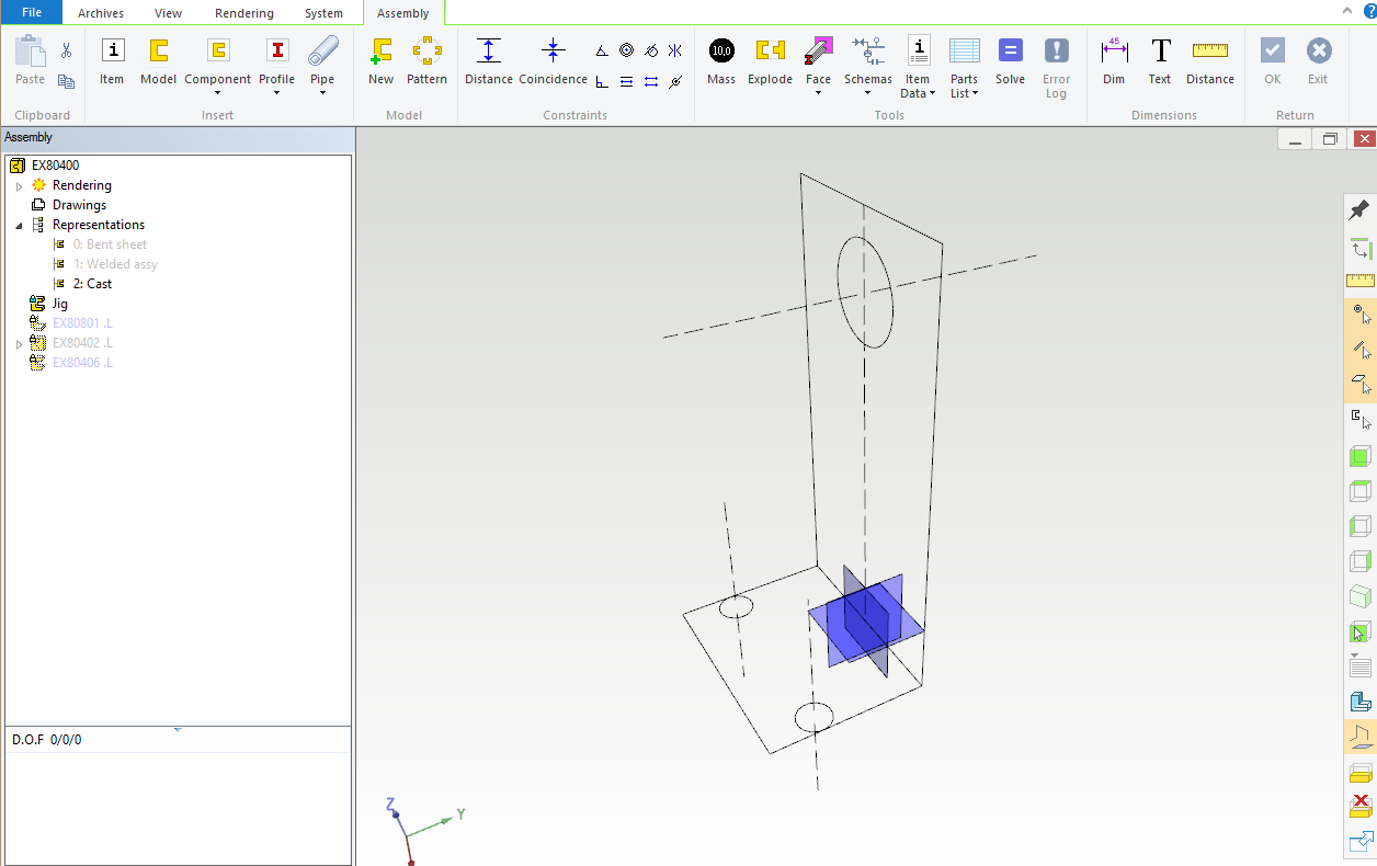
Picture 1: Part skeleton with overall dimensions and hole centerlines. The next three models all are made using the skeleton geometry, but the models are manufactured in three different ways.
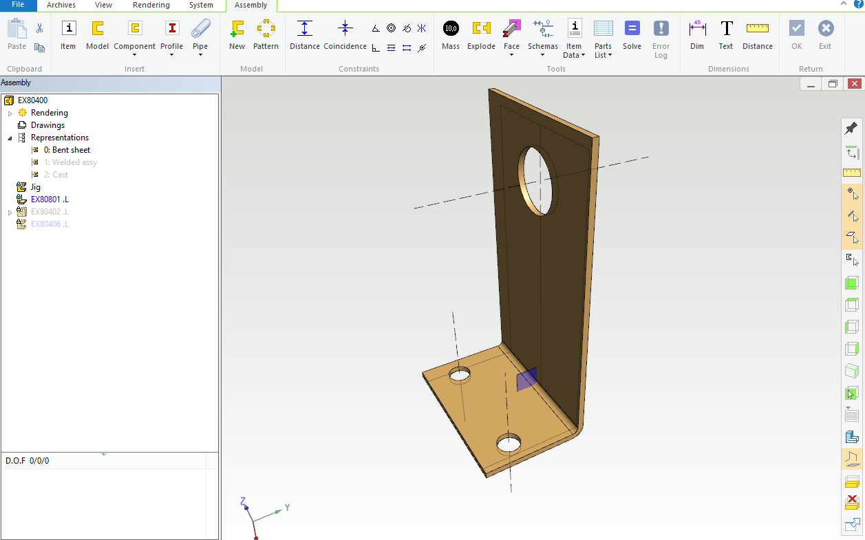
Picture 2: Bracket made of sheet metal.
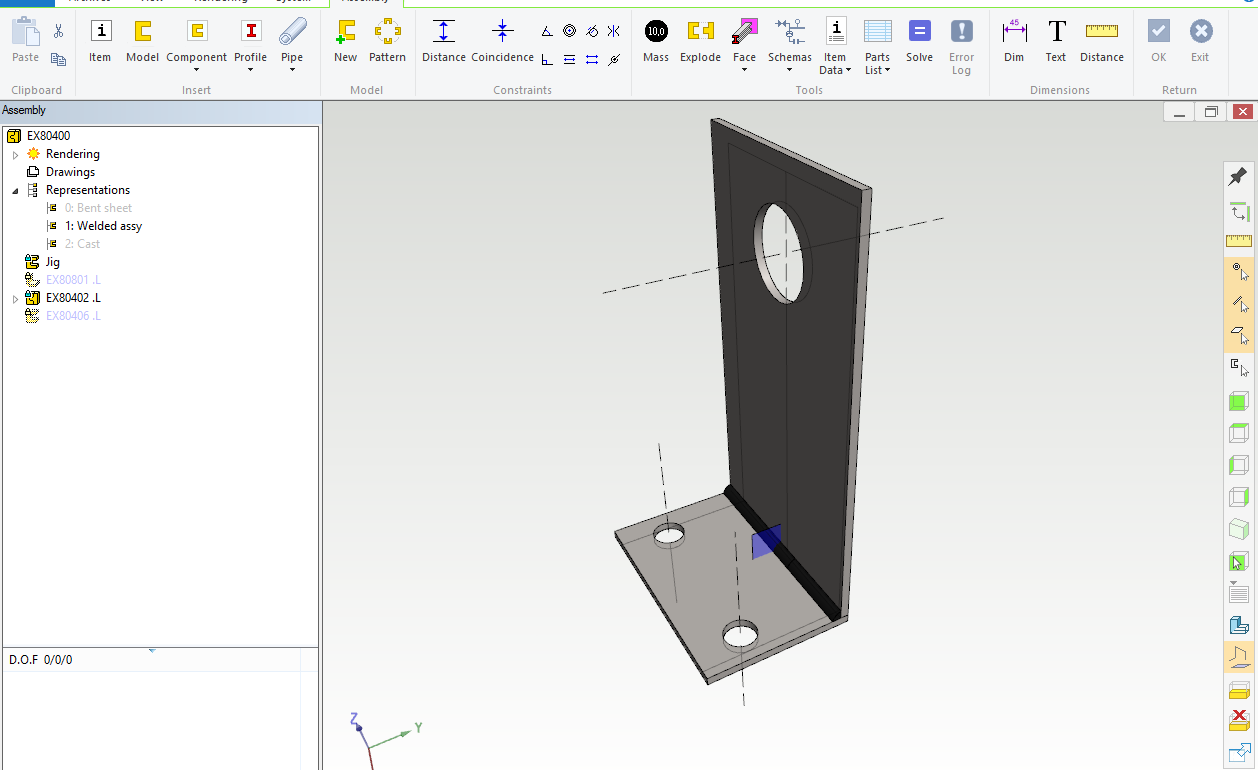
Picture 3: Bracket made as a sheet metal assembly from two parts and a weldment.
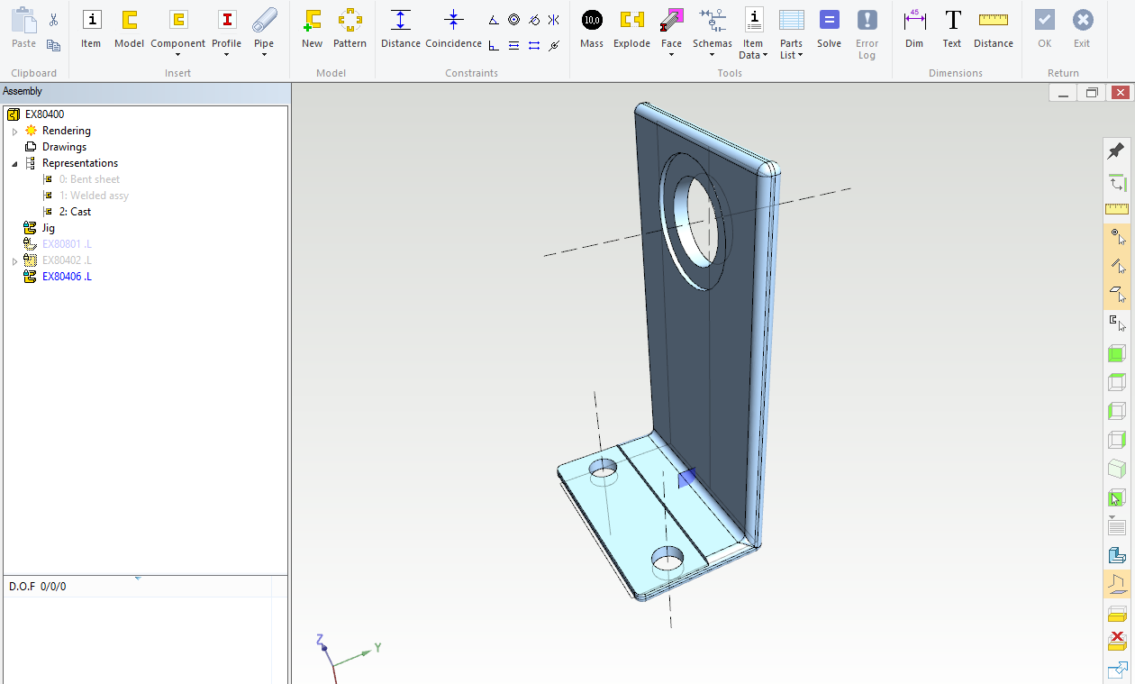
Picture 4: Bracket made by casting.
