
Vertex G4 delivery contains drawing templates. Using these templates you can customize your own templates e.g. add company logo and contact information.
Copy templates to customer directory
Standard templates are situated in directory ..\system\symbols\Sheets. Before modifying standard templates copy necessary sheets into customer directory ..\shared\symbols\Sheets. Then you can drag and draw templates into G4 window to modify them. Modify one template, test that it works and then copy the modified part to other templates.
Change company logo
You may only want to change company logo to templates. You can add your own logo in many different formats: .gif, .tiff-, .jpg or .bmp. Of course you can also design the logo using G4. Before you can edit the template you have to explode the group binding the template.
1) Select the template (green color)
2) Select Explode group by using the right mouse button
3) Delete old logo
4) Add / draw new logo
5) Save new template to the symbol library
Import new logo using Raster Images > Raster. Scale the image by pressing F8 or selecting K from the pop up menu.
Levels
Add lines and texts to the level 9 if they are not depending the language. Add language depending texts to separate level. In standard templates english texts are situated to the level 31.
Archive data
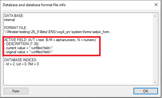
It is possible to add any information from drawing archive to the drawing template. You can find out drawing field name by clicking the field with right mouse button.
If the drawing has a project connection, you can also get project archive information to the drawing by using PROREG-prefix (#PROREG.CUSTOMER#).
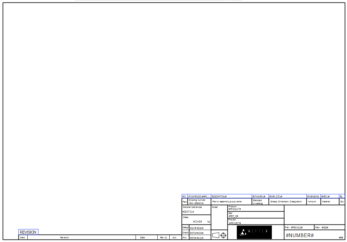
Add archive data to the template heading
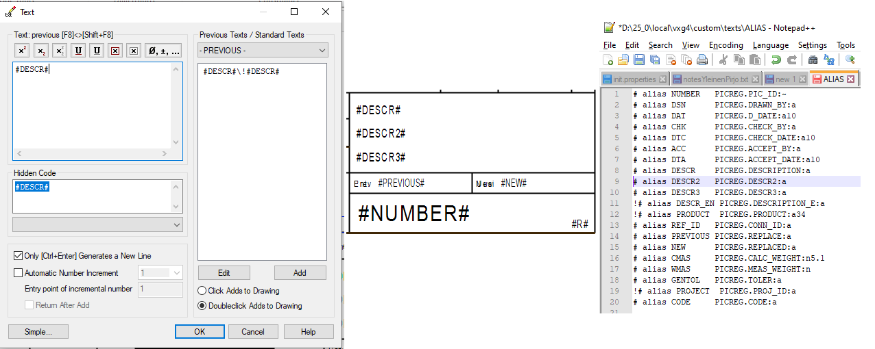
Template heading texts are coded between #-marks (e.g. #DESCR#). This code (text macro) refers to the file ...\systems\texts\ALIAS. Lines in file ALIAS refers to the drawing archive fields.
Example: Description to the template heading
1) Add text to the desired level
-
Copy existing macro and modify copied macro
2) Fill in Hidden Code to the text properties (#DESCR#)
3) Insert row to ALIAS file
-
Check description field name from drawing archive (DESCRIPTION)
-
Check database field types below (e.q. a:40)
-
Remember to save ALIAS from directory system to custom -directory custom\texts\ALIAS
4) Save new template to the symbol library
Database field field types
Type is written after the field name, e.g. PICREG.PRODUCT:a34
|
Example |
Description |
|---|---|
|
a |
alphanumeric field |
|
a20 |
alphanumeric field, length 20 characters |
|
n5 |
numeric field, integer |
|
n6.2 |
numeric field, max 6 integers, 2 decimals |
The code (text macro) can also contain visible text. E.g. code Draw.Rev:#R# is printed to the drawing as Draw.Rev:3 (if the drawing has revision 3).
Modify the parts list table
Parts list is based on a table, different languages are situated in different layers.
You can adjust the length of the table cells and deside whether to cut the text inside a table cell or divide it into separate lines. The lengths of the characters are not the same so the number of characters of one table cell is not contant.
In standard Vertex templates (system/symbols/Lomakkeet) there are 2 tables in different layers:
-
Finnish table is in the layer 4
-
English table is in the layer 31
Parts list table:

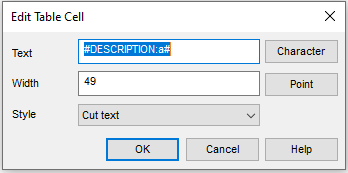
Edit the table cells:
-
Text: Free format text
-
Length The lenght of the field in mm.
-
Style how to handle long texts
-
Cut text
-
Cut text...
-
Slip into rows
-
-
With the Point button you can position the lenght of the cell. Click two vertical points from the drawing. The length of the cell is defined by these 2 points.
The first row is selected the be modified.
Specify the properties of the table texts
Specify the part list fields and the format.
Select the table and then select from the pop-up menu Ominaisuudet.
Teksti on muotoa:
#CPNO:a#¡[PICNO?#CODE:a#;#PIC_ID:a#]¡#DESCRIPTION:a#¡#STANDARD:a#¡#MARK_STD:a#¡#DIMENSIONS:a#¡#SPEC:a#¡#QUANTITY:n#
-
Text macros (e.g. #CPNO:a#) refer directly to the field of the item database
-
Field separator is marked as ¡
-
Structure [PICNO?#CODE:a#;#PIC_ID:a#] specifies that first the item code is printed and if it is empty the drawing number is printed
-
:a specifies the number of marks to be printed
-
:a4 4 marks are printed
-
:a all marks of the field are printed
-
:n corresponding definition of a numeric field
-
NOTE: The fields must be defined in database d_COMPONENTS.
Change table to the partlist format
1) Select the table
2) Select Change to partlist format from the pop-up menu
3) Select Parts list to drawing
Save new template to the symbol library
After editing the template save it to the symbol library.
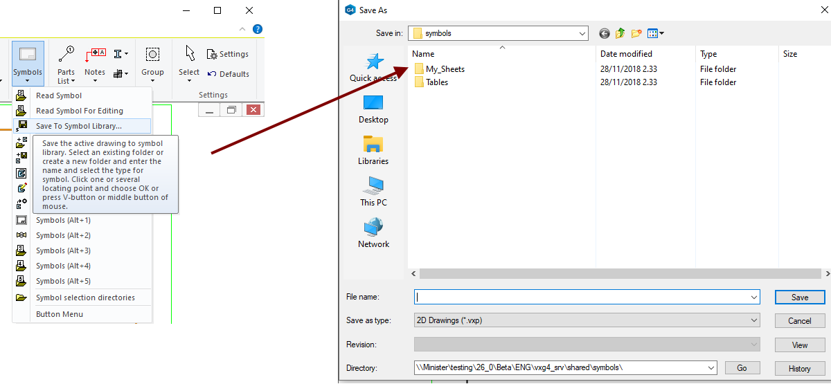
1) Select Symbols
2) Select Save to symbol library
3) Select the directory shared\symbols\... and give the file name
4) Select the symbol type Autom. updated sheet
5) Select position points
6) End saving by selecting Ok