

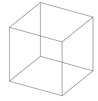
Exercise 3: Framework
This exercise was carried out with version 27.0 (Vertex 2021).
In this exercise you will learn to
-
3D sketching.
-
Profile cross-section attachment point change.
-
Rotation of the profile cross section before placement.
-
Leaving a gap at the ends of the profile while the profile is being added.
Functions to be used:
-
New local part of the assembly.
-
Sketching: Two-point rectangle and dimensioning.
-
New sketch > 3D sketch.
-
Add > Profile.
-
Select reference point (from the profile cross section, before adding the profile to the guide curve).
-
Rotate right/left (rotate the cross section before adding to the guide curve).
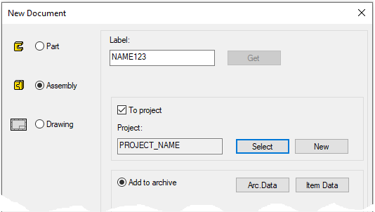
Create a new assembly
-
File > New > Assembly.
-
Enter the label (which is also the name of the model and by default will be the name of the drawing).
-
Enter the archive information by clicking Arc.Data.
-
Select the project where the model will be saved.
-
OK.
-
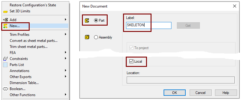
Create a new local part (Skeleton - Guide curve)
-
Right-click function: New > Part
-
Enter a name, eg SKELETON or JIG.
-
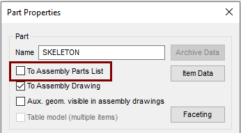
Define that the control curve part does not appear in the parts list
-
Right-click function: Properties
-
Deselect the settings: To Assembly Parts list, because this part is not desired in the parts list, after all it is a completely "intangible" part.
Model the guide curve of the bottom
-
Right-click function: New Sketch > To horizontal (XY) plane.
-
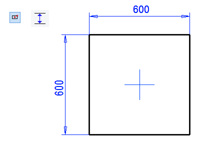
Sketch the rectangle symmetrically to the central cross.
-
Add distance constraints: 600.
Operation
-
Guode Curve.
Model the guide curve of the top
-
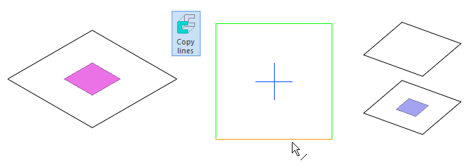
Restore the Horizontal(XY) plane, if it is not already visible. (From Feature Tree: Restore).
-
Click the Horizontal(XY) plane.
-
Right-click function: New Sketch >Parallel.
-
Enter 600 as the dimension and HEIGHT as the formula.
-
Right-click function: Line > Copy to Sketch Plane or

-
Click the lines and finish copying with the right-click function OK.
Operation
-
Guode Curve.
Turn the model so that you can see the guide curves for the bottom and cover.
Model the vertical lines
-
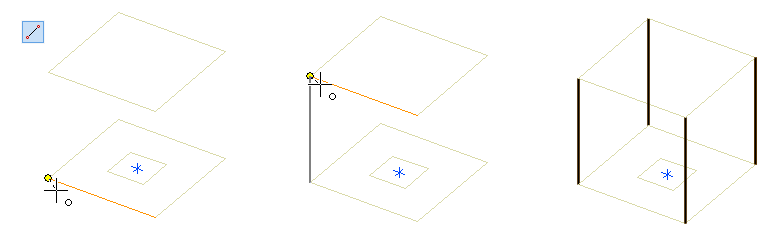
Right-click function: New sketch > 3D sketch.
-
Sketch the four lines so that the cursor grabs the ends of the lines.
-
Exit the 3D sketch with the right-click function OK.
-
The operation is not requested, so the 3D sketch always automatically becomes a guide curve-type geometry.
-
Exit from part to assembly
-
OK.
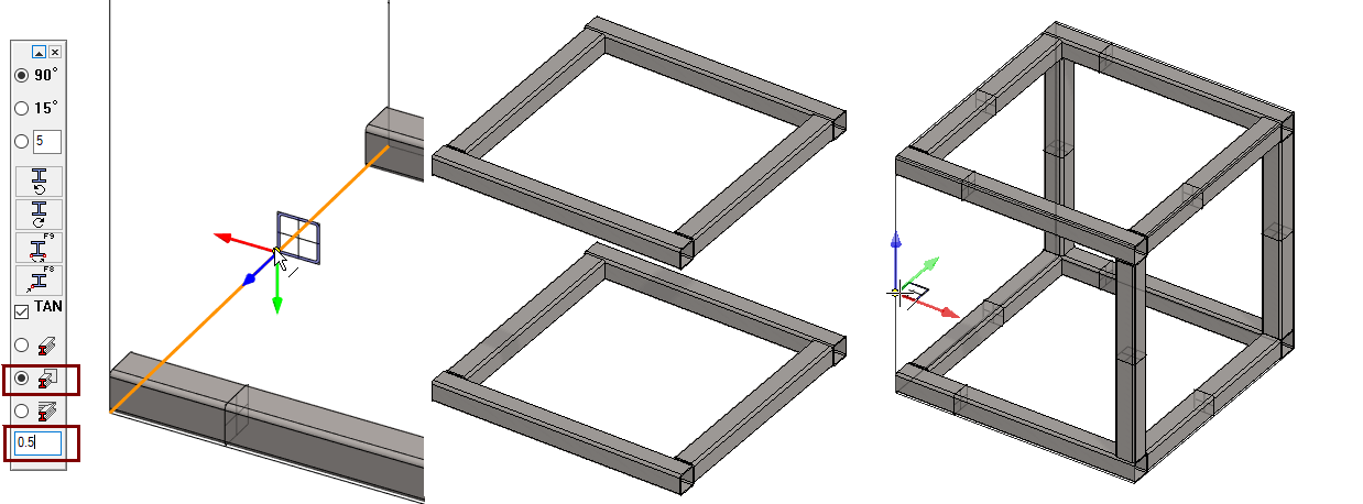
Add the base and top profiles in the X-axis direction
-
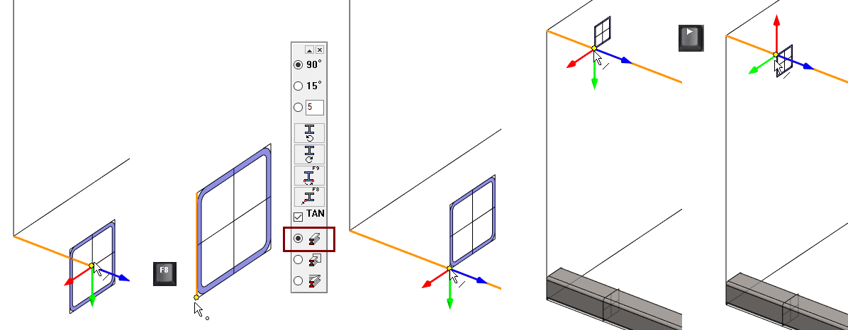
Right-click function: Add > Profile.
-
Select the profile from the library Profiles > Thinwall_tub_spar > SSAB_10219_SQUARE.
-
Select size: SSAB_50x50x2.
-
Change the anchor point from the center to the corner point, press


-
Click anchor point (bottom corner).
-
Select the two bottom edge lines so that the profile is inside the guide curve geometry.
-
-
To change the anchor point to another corner point, press
-
Click anchor point (upper corner).
-
Select the two top edge lines so that the profile is inside the guide curve geometry.
-
-
Because the anchor point is already in the corner, you can
-
alternatively also rotates the profile to the correct position

-
The profile is positioned on the line from its point of attachment so that the blue axis points in the (positive) direction of the line.
-
Right arrow

-
Left arrow

Add the rest of the profiles
-
Switch to trimming mode on the: Trim automatically to face.

-
If you want to leave a small gap between the end of the profile and the face of the associated profile, eg due to a weld seam, enter the size of the gap in the lowest field of the menu.
-
In this example, 0.5 (0.5mm) means that the profile becomes one millimeter shorter than the distance between the associated profiles, as the gap is left at both ends.
-
Create a drawing for the assembly
-
Look at detailed instructions: the Modeling parts course exercise 5 Drawing of Model.
-
Save the drawing.
-
Remove it form Vertex desktop.
Save the model
-
File > Save or click


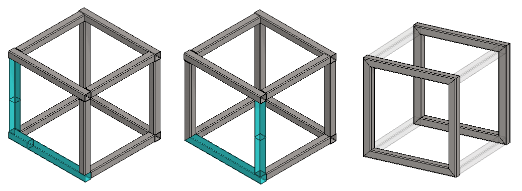
Make another version of the framework
In the second version, the framework is the same size, but the profiles are trimmed so that no open pipe ends are visible.
Save the model as a new model
-
File > Save as new
Trim profiles to the miter
Trim the front and back profiles to the miter.
-
Click two profiles (the latter
-
Right-click function: Trim profiles > To Edge or from the ribbon: Miter (in the Trim group).
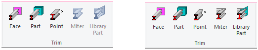
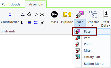
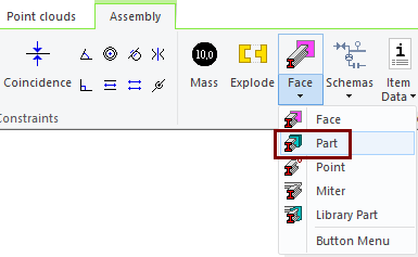
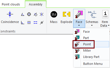
Fase = Once one or more profiles are selected, this option can be selected and click to a face to which the profiles will be trimmed.
Part = Once one or more profiles are selected, this option can be selected and click to a part to which the profiles will be trimmed.
Point = Once one or more profiles are selected, this option can be selected and click to a poin to which the profiles will be trimmed.
Miter = Once two profiles are selected, this option can be selected to trim the profiles to the miter.
Library Part = Once two profiles are selected, this option can be selected, followed by a tool that is positioned at the intersection of the profiles and to which both profiles are then trimmed.
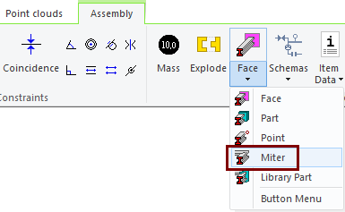
Use the trimming tool found on the ribbon: Miter. when you want to repeat trimming in succession for several profiles.
-
Click profiles to trim each other.
-
Repeat until all required profiles have been trimmed.
-
First, click the target face or faces.
-
End the selection of fases with the right-click function: OK.
-
Click the profile or profiles you want to trim.
-
Perform trimming with the right-click function: OK.
-
First, click the target part or parts.
-
End the selection of parts with the right-click function: OK.
-
Click the profile or profiles you want to trim.
-
Perform trimming with the right-click function: OK.
-
First, click the target point.
-
Click the profile or profiles you want to trim.
-
Perform trimming with the right-click function: OK.
Open the drawing of the model
-
Click the Drawing from the feature tree.
-
Right-click function: Open Drawing.
-
Correct the part numbering if necessary.
Save the model
-
File > Save or click
Download the framework model (VX_PROF3.vxz) here.