
Overview
In cold-formed steel (CFS) design, localized, distortional, and global buckling govern member capacity under axial compression and flexure. To accurately calculate the critical elastic buckling load or moment within the Vertex BD FEA module, the effective buckling length must be correctly defined based on appropriate kinematic boundary conditions.
In Vertex BD, the effective length can be defined by connections, by members or by nodes. By using these different defining modes, user can determine whether or not a connection node is to be used to shorten the effective length of the member, depending on the type of buckling.
This article details the algorithmic differences between these three boundary condition definitions and provides engineering criteria for selecting the appropriate method based on structural configuration.
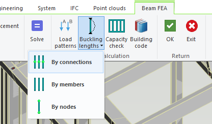
By connections
-
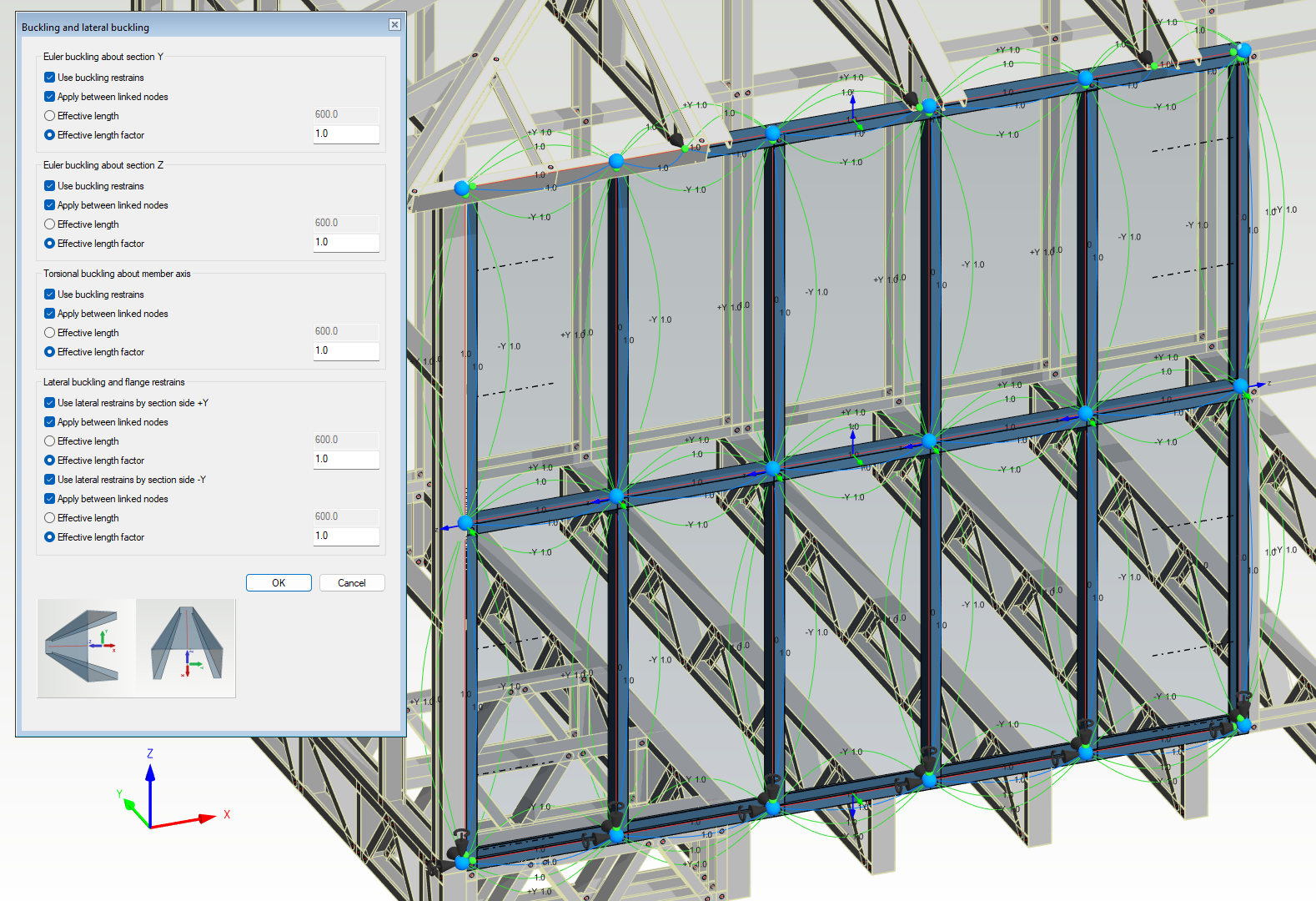
User defines the buckling length on selected members.
-
User has full control on effective length properties.
-
Apply between linked nodes is in effect for all buckling types regardless of the connection type, as long as the property is checked.
-
The system will detect all linked nodes and defined free nodes within the members and apply buckling length according to the properties defined by the user.
By members
-
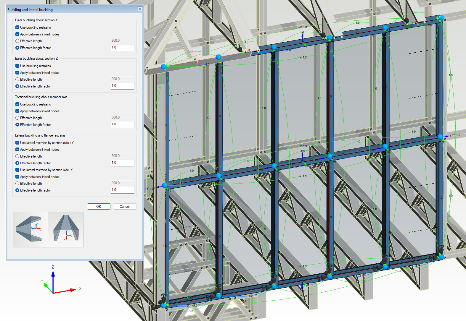
User defines the buckling length on selected members.
-
User has partial control on effective length properties.
-
Even with Apply between linked nodes checked, system will determine whether or not it applies based on the node constraint properties.
-
For example, in the wall panel shown on the right, the buckling length for Euler buckling about section Z for the studs is the whole length because the blocking cannot provide lateral support when the studs are buckling out-of-plane.
By nodes
-
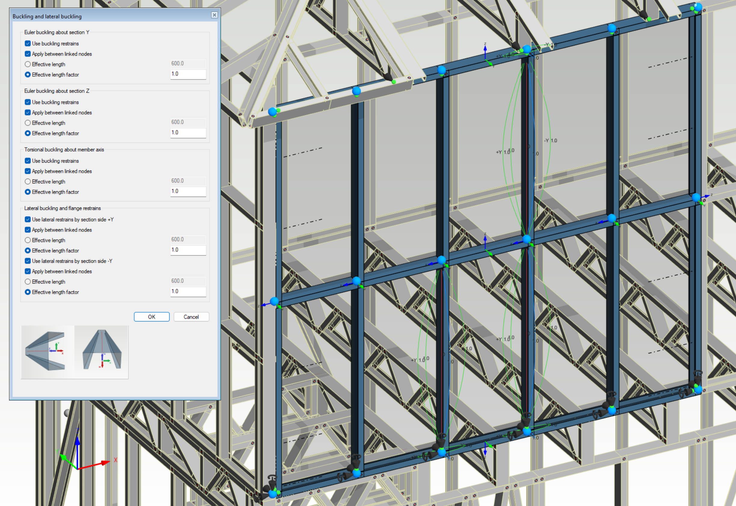
User defines the buckling length by manually selecting the end nodes of the member.
-
User has full control on effective length properties.
Summary
Ultimately, choosing the right buckling length definition in Vertex BD depends on the structural configuration of your design and the specific level of control required.
-
The By members method is recommended for most general applications, as it introduces smart, automated safeguarding by evaluating whether physical components (like blocking) provide true structural restraint, keeping capacity estimates safely on the conservative side.
-
In contrast, the By connections method grants full manual control and is ideal when accounting for external restraint conditions not explicitly modeled, such as wall sheeting or cross-member battens.
-
Finally, because the By nodes method requires manual selection and is highly labor-intensive, its use should be restricted to isolated scenarios involving only a small number of members.
Understanding these algorithmic differences ensures accurate FEA simulations, preventing overestimating member capacity and ensuring compliance with cold-formed steel design standards.