
General Information
Vertex wall engineering is a table-based design tool aimed at checking the capacity of wall frame components against the vertical loads from the structures above the walls. The capacity check includes headers, studs with/without noggings, and lintels. The unfactored reaction loads from the truss above the wall panels are collected and allocated to the location of the contact. The loads will then be factored and combined. The system will work out the worst case and compare that to the capacities of the components defined in a load table, which can be specified by the engineer.
Vertex wall engineering tool is a selectable option. Please check the option list in This Software Versions to find Wall Practical Engineering. If that is not in the list, you will need to contact us to activate the tool for your license.
The example capacities in the load tables are for reference only. The capacities of the wall frame components in the load table should be approved by a certified engineer. The capacities added to the load table should be factored or they should be from experiments adhered to the code.
The tool is intended for basic wall framing structures. Complicated wall structures, such as overlapping lintels, bulk heads and beam pockets, should be checked by an engineer manually or using FEA tools in Vertex BD. Vertex wall engineering does not check horizontal racking forces and loads perpendicular to the wall panel. Please use FEA and Wall Wind Bracing tools for those loads. You can find some case studies here.
Design Requirements and Assumptions
-
Truss engineering must be performed and finalised beforehand.
-
Walls must be panelised and framed.
-
The boundary conditions of the walls are assumed intact.
-
End studs in between wall panels are assumed to be sufficiently connected.
-
Point loads, line loads and continuous support loads are considered in wall engineering.
-
The collected reaction loads are from the truss directly above the wall panels and they are not accumulated. For example, for two-storey buildings, only the reaction loads from the floor trusses are checked for the ground floor. If more loads a needed, user can choose to add manual loads on the floor trusses in truss engineering beforehand.
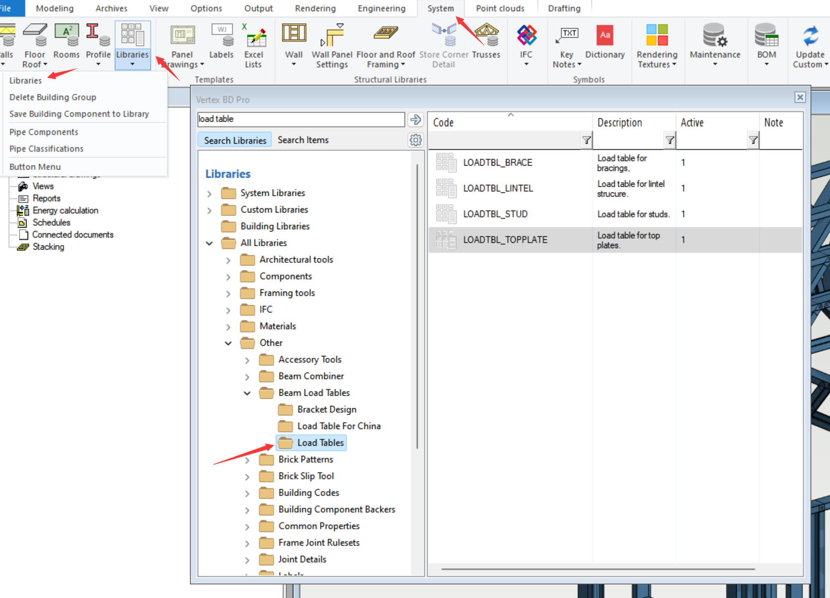
Load Table
Load table is located in system library. Administrative access is required for modifications. To learn how to obtain administrative access, please contact us.
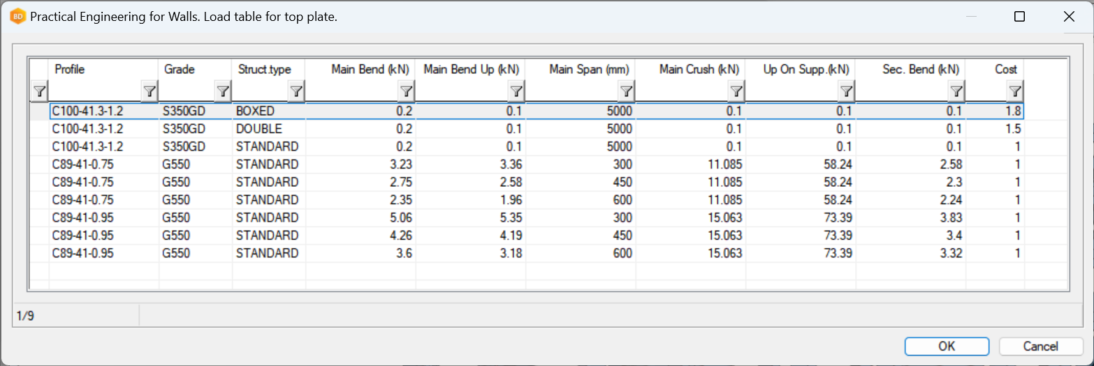
Top Plates
Identification
Profile: Profile code for the top plate
Grade: Profile steel grade for the top plate
Struct.type: Whether or not multiple profiles are used for the top plate
Main Span: The dimple-to-dimple distance between support
For Struct.type, user can select BOXED, DOUBLE or STANDARD in the pull-down menu. User can also type in TRIPLE if triple-piece is needed.
When the exact span of the top plate is not found in the load table, system will select the next larger one to be on the safe side.
Capacities
Main Bend: Vertical load down in span
Main Bend Up: Vertical load up in span
Main Span: is distance between studs
Main Crush: Vertical load down at support (stud)
Up On Supp.: Vertical load up at support (stud)
Sec. Bend: Horizontal load in span
When loads are mid-span, main bend and main bend up capacities are used, while main crush and up on supp. are used when loads are directly on top of support from node points, e.g., studs. TOP_PLATE_SUPPORT_TOL in pcec_setup is used to set tolerance for system to determine whether or not the load is on top of support. The default is 20 mm.
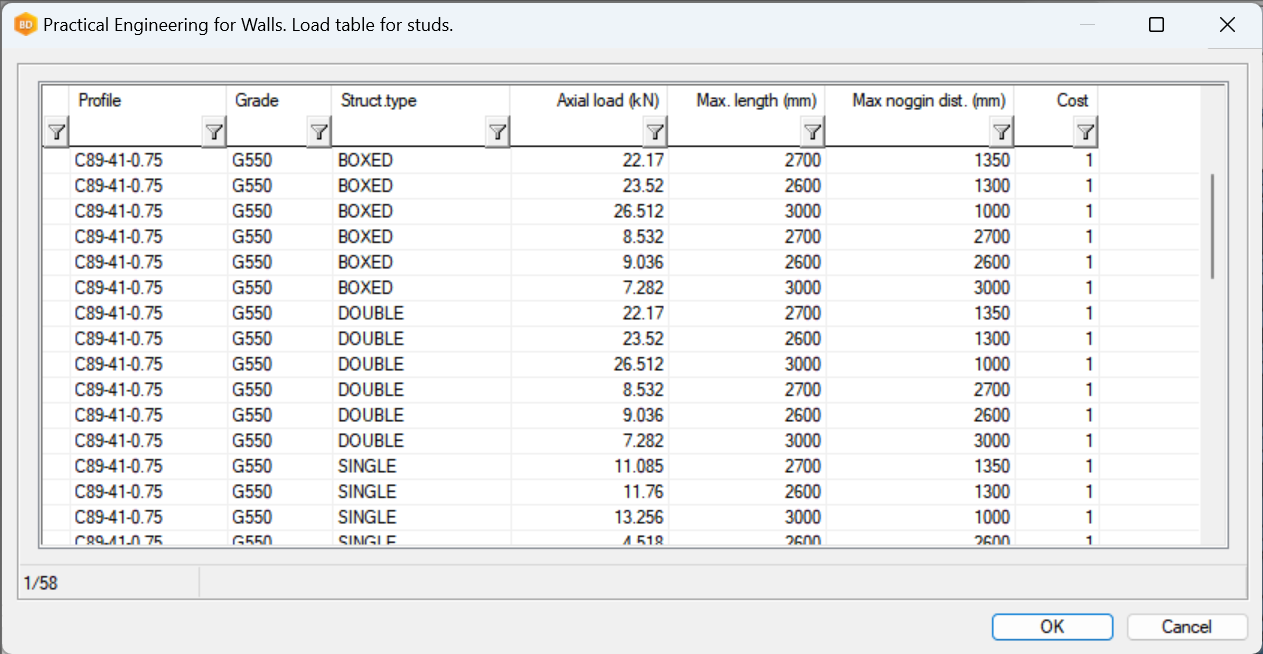
Studs
Identification
Profile: Profile code for the stud
Grade: Profile steel grade for the stud
Struct.type: Whether or not multiple profiles are used for the stud
Max. length: The total length of the stud.
Max noggin dist.: The maximum distance between two connected nodes on the stud.
Double and triple stud configurations are recognised when the distance in between the studs is smaller than a tolerance in vxsettings (STUD_GROUP_TOL). By default, the tolerance is 0.5 mm, meaning no gap is allowed.
When the exact length for Max. length and Max noggin dist. is not found in the load table, system will select the next larger one to be on the safe side.
Capacities
Axial load (kN): The axial compression capacity in kN.
If required, the tension capacity check for the studs will need to be performed manually by an engineering.
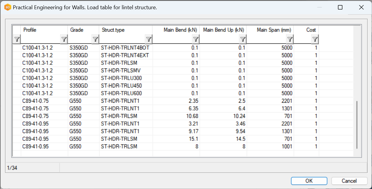
Lintels
Identification
Profile: Profile code for the lintel
Grade: Profile steel grade for the lintel
Struct.type: The code of the lintel type
Main Span: The width of the lintel opening measured by end dimple to dimple of the header.
When the exact width of the lintel is not found in the load table, system will select the next larger one to be on the safe side.
Capacities
Main Bend: The allowable combined down force on the lintel
Main Bend Up: The allowable combined uplift on the lintel
The top plate in the lintel is checked separately. The maximum node distance is used as main span to identify the top plate. The king studs are also checked separately.
Collected Loads
Top Plate
PracticalPointLoad = max load between supports
PracticalUpliftPointLoad = max uplift load between supports
PracticalSecondaryPointLoad = max lateral bending load between support
PracticalSupportPointLoad = max load on support
PracticalUpliftSupportPointLoad = max uplift load on support
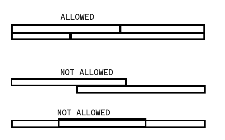
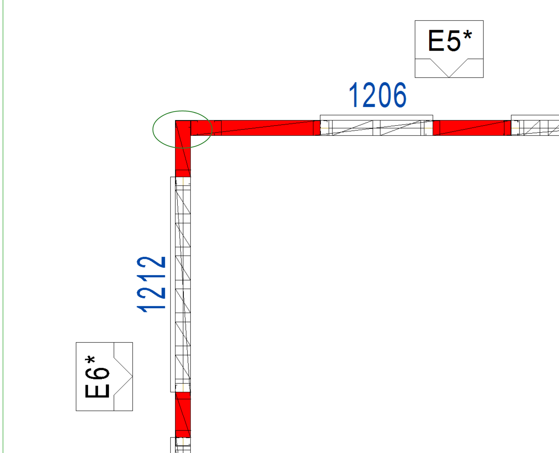
The top plate can have many pieces, but the entire top plate must be homogeneous. Please refer to the diagram on the right.
Header/Lintel
PracticalPointLoad = max load on header/lintel (sum of all loads on lintel)
PracticalUpliftPointLoad = max uplift load on header/lintel (sum of all loads on lintel)
Stud/Stud Group
PracticalAxialLoad = max load on stud/stud group
Steps of Vertex Wall Engineering
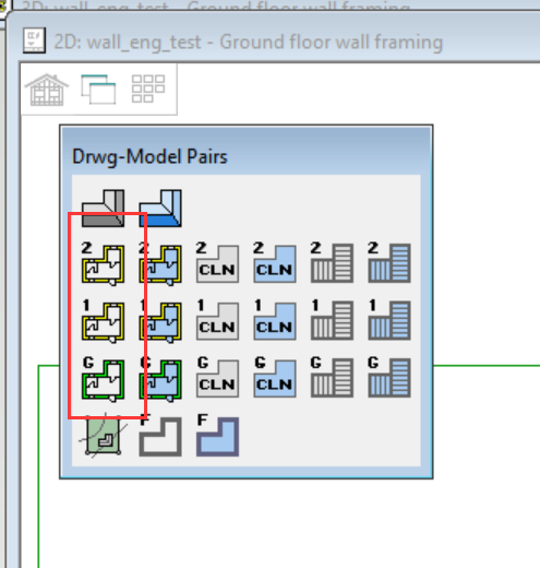
Switch to 2D wall model pair.
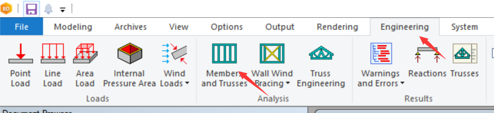
Select Members and Trusses under Engineering ribbon.
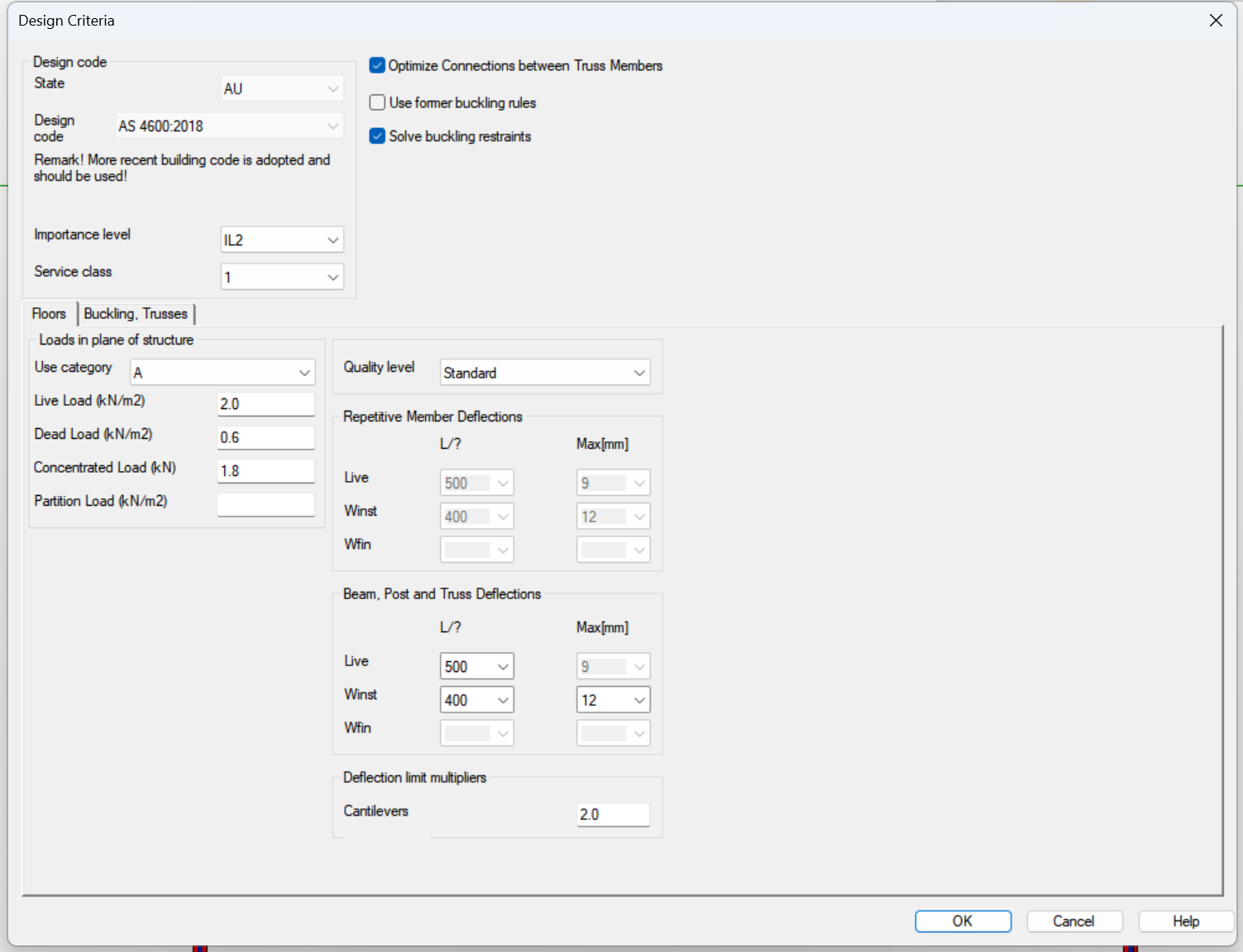
If the structure is deemed ready for wall engineering, the Design Criteria dialogue will appear. You don't have to change any fields in this dialogue, as all loads are collected from truss engineering. Click OK to initiate the capacity check.
System will prompt users to select objects to design. Select all the walls you want to include in the capacity check. Only load-bearing walls can be selected.
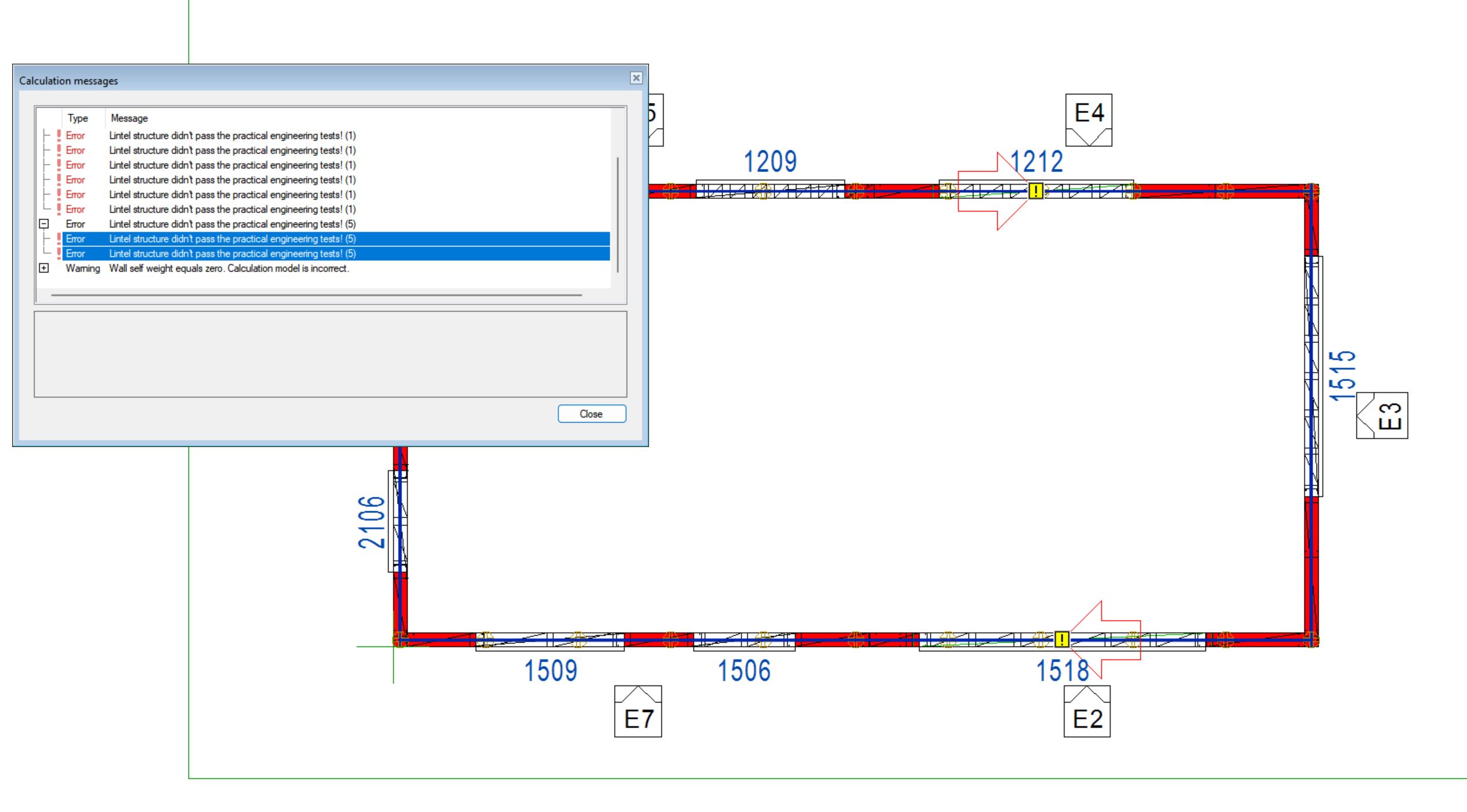
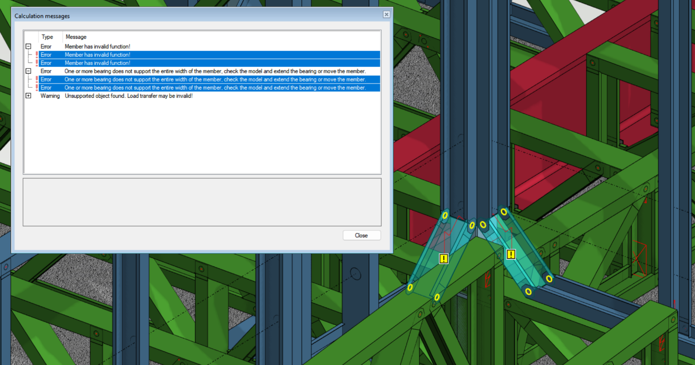
After the capacity check is finished, Calculation messages will appear. You can highlight any errors to investigate their origin, and they will be pointed out in the wall layout. You can also open the calculation messages in both 2D and 3D model pair after capacity check. The instruction is in the next section of this page.
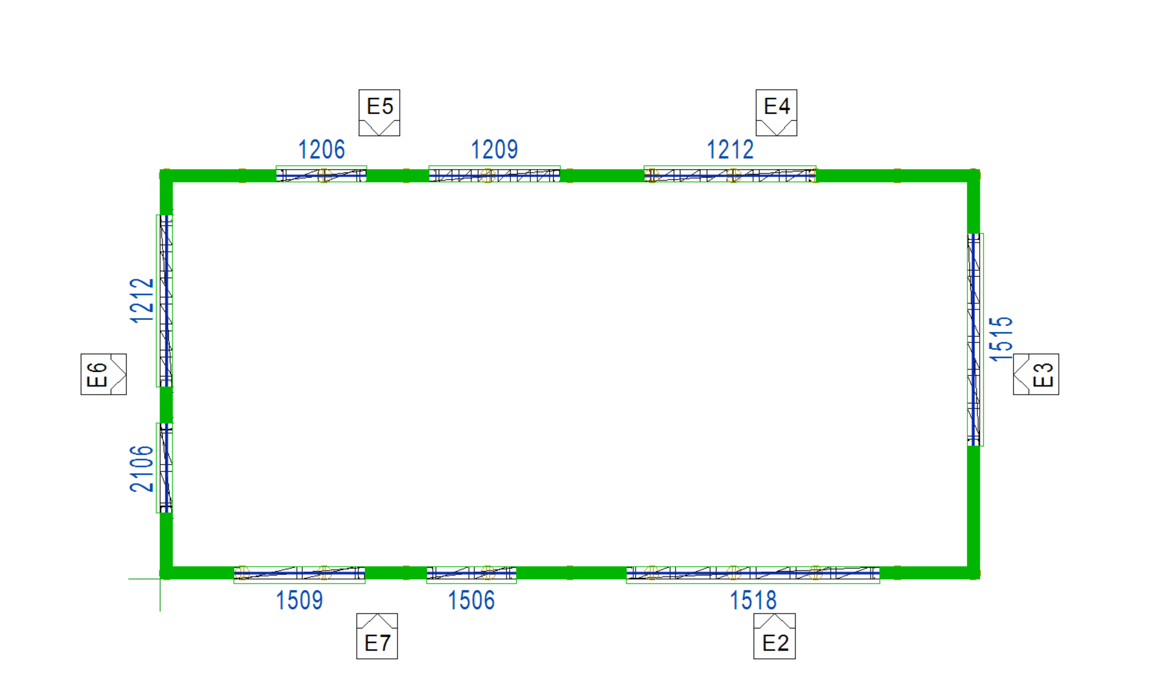
Select the locate the result schedule in the wall layout.
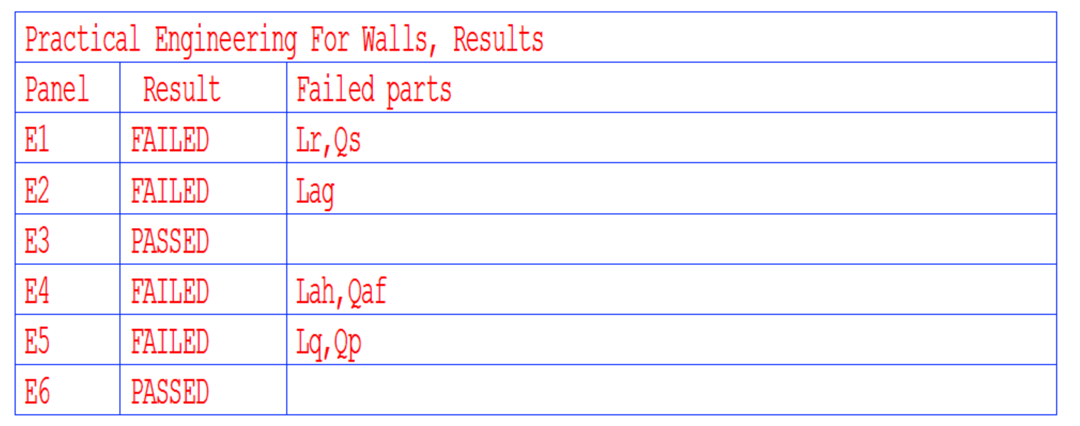
Results and Outputs
User can find the passed and failed wall panels in the result schedule. The labels of the failed parts can be identified in the wall panel drawings.
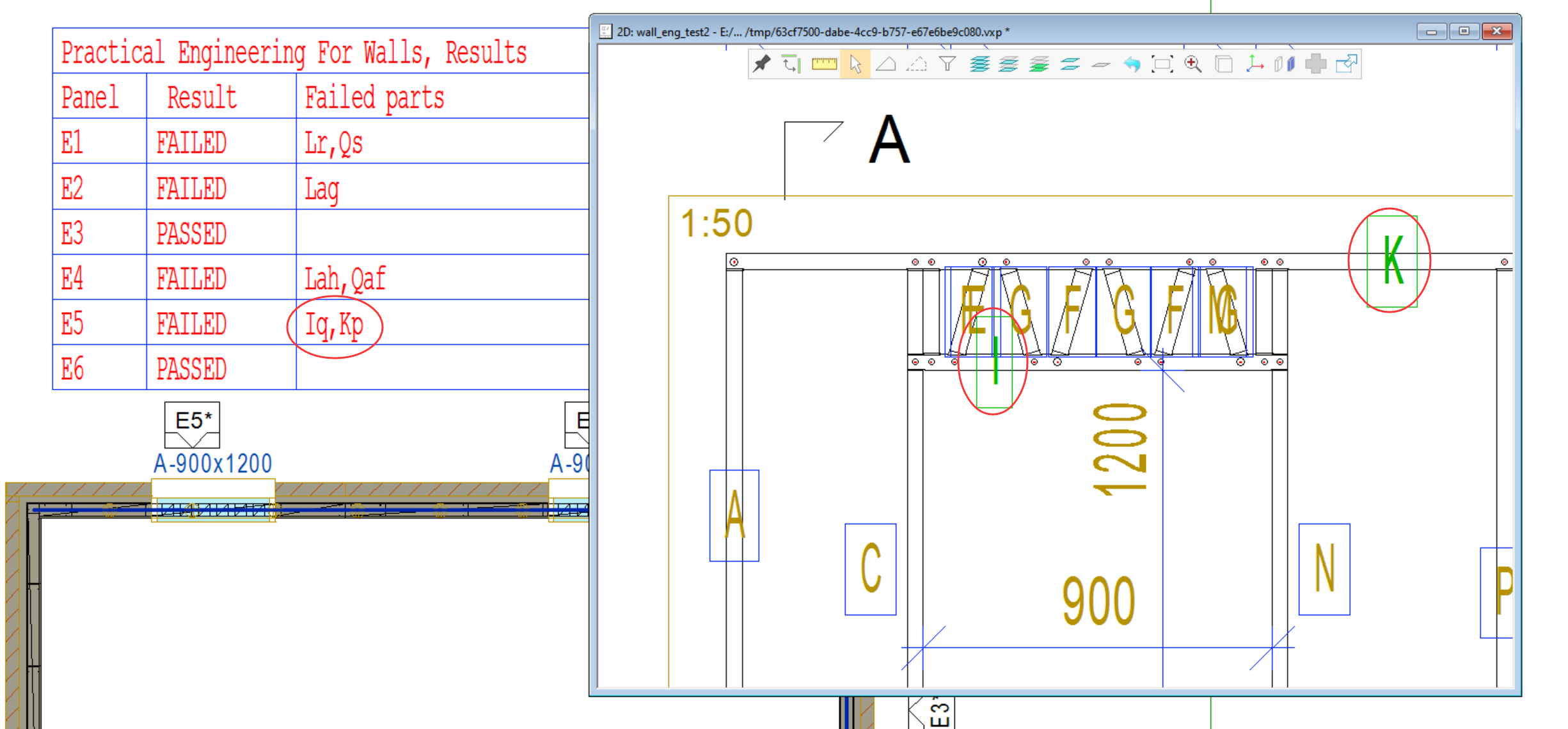
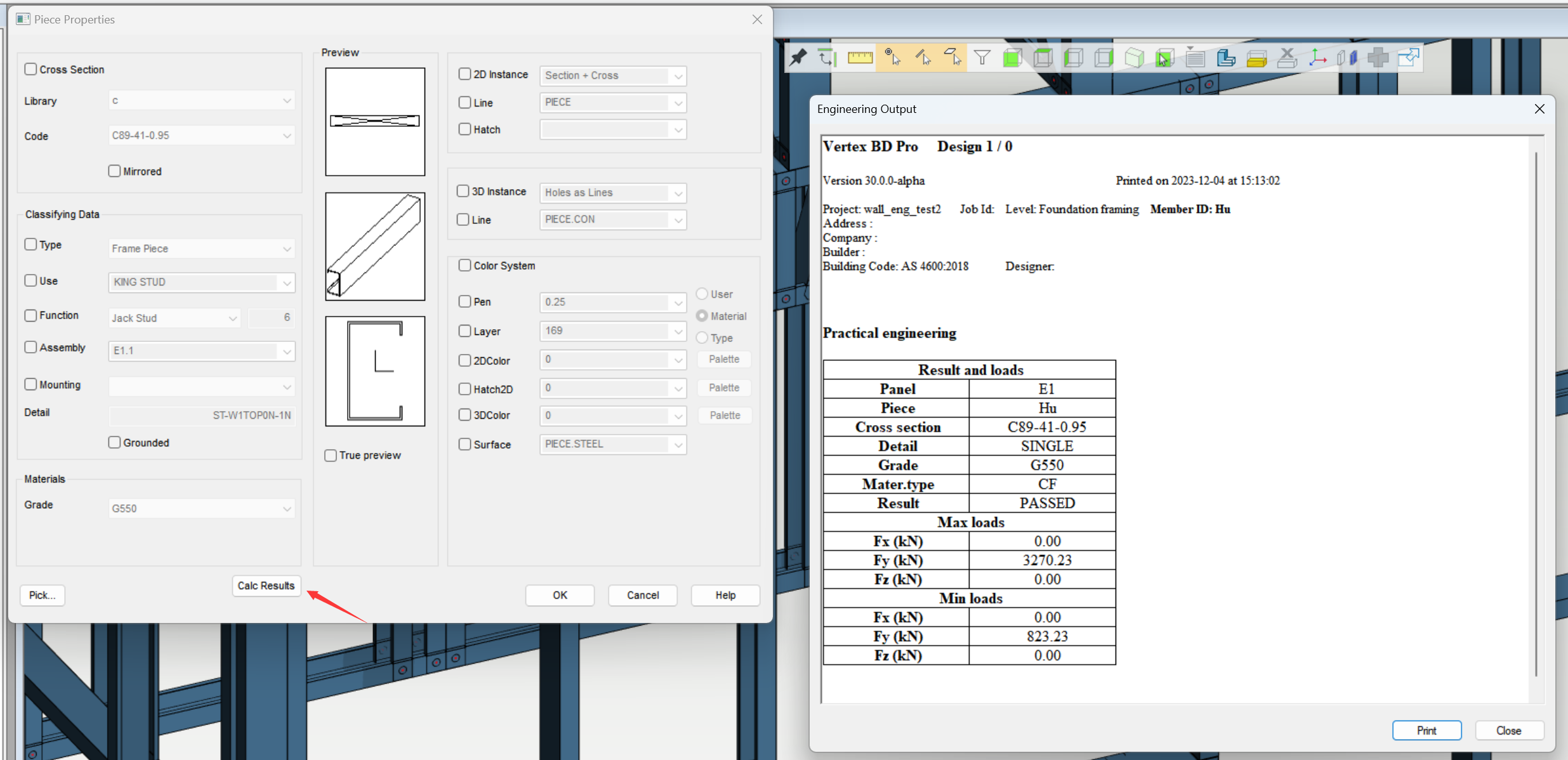
The calculation details for pieces can be found in the property in the right-click menu. You can find the identification of the piece and the maximum load being used. The loads in the table are factored.
Trouble Shooting
Common Warnings and Errors
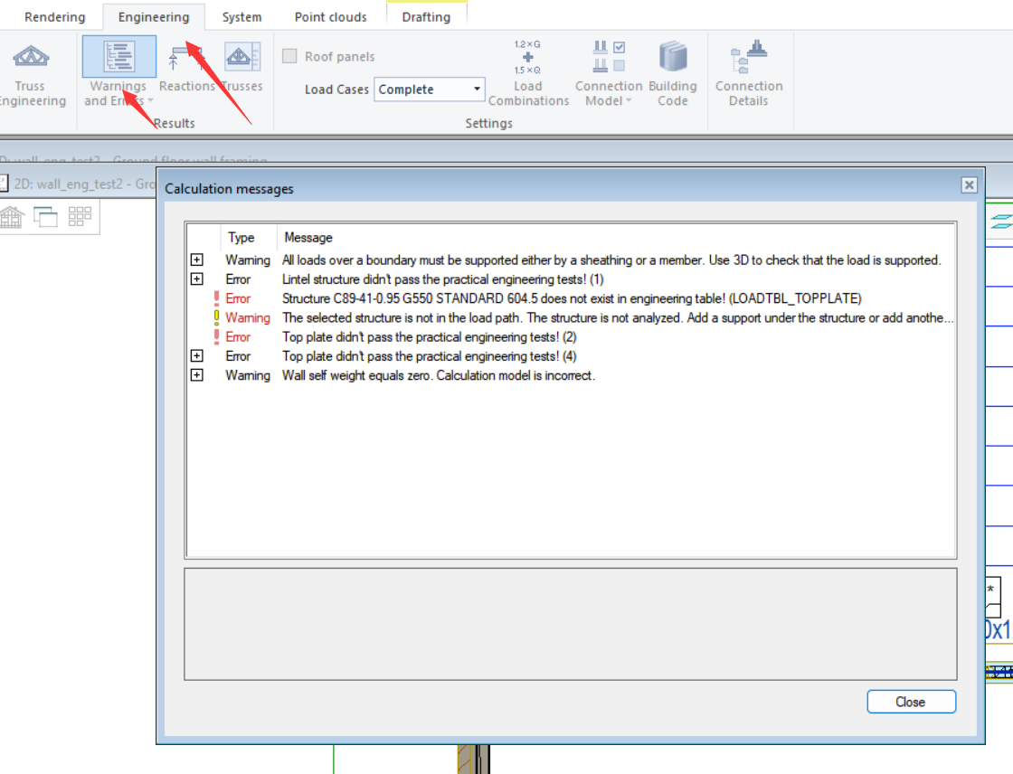
After performing wall engineering, a calculation message with warnings and errors would appear. You can also find it later in Warnings and Errors under the Engineering ribbon. You can identify the pieces causing the errors in both 2D and 3D model pairs, making troubleshooting much easier. In this section, some of the most often seen warnings and errors are explained.
Warning: Some loads located outside top plates. In wall corner other wall might carry those loads.
-
This warning message points at the the walls with corner details that involve other wall panels. It means that the loads at the corner are taken by the other wall panel. This message does not impact the engineering process. In the current example, the vertical wall panel extended and this warning would point at the horizontal wall.
Warning: All loads over a boundary must be supported either by a sheathing or a member. Use 3D to check that the load is supported.
-
This warnings message points at the loads the system deems unsupported. This message does not impact the engineering process. Please check the source of this message and ensure it does not point at loads that should be included in the capacity check.
Warning: The selected structure is not in the load path. The structure is not analyzed. Add a support under the structure or add another structure on top it.
-
The system does not detect any reaction loads on the structure with this warning message. This message does not impact the engineering process. Please double check that reaction loads are transferred correctly from the trusses to the wall panels.
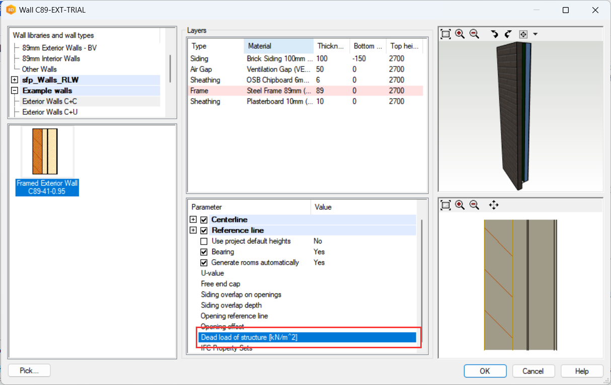
Warning: Wall self weight equals zero. Calculation model is incorrect.
-
The self-weight of the wall is not found in the wall engineering. Please enter the self-weight of the wall in the wall properties.
Wall's self weight do not affect to top plate, but it is taken account with lintels.
Error: A member has invalid function! One or more bearing does not support the entire width of the member, check the model and extend the bearing or move the member.
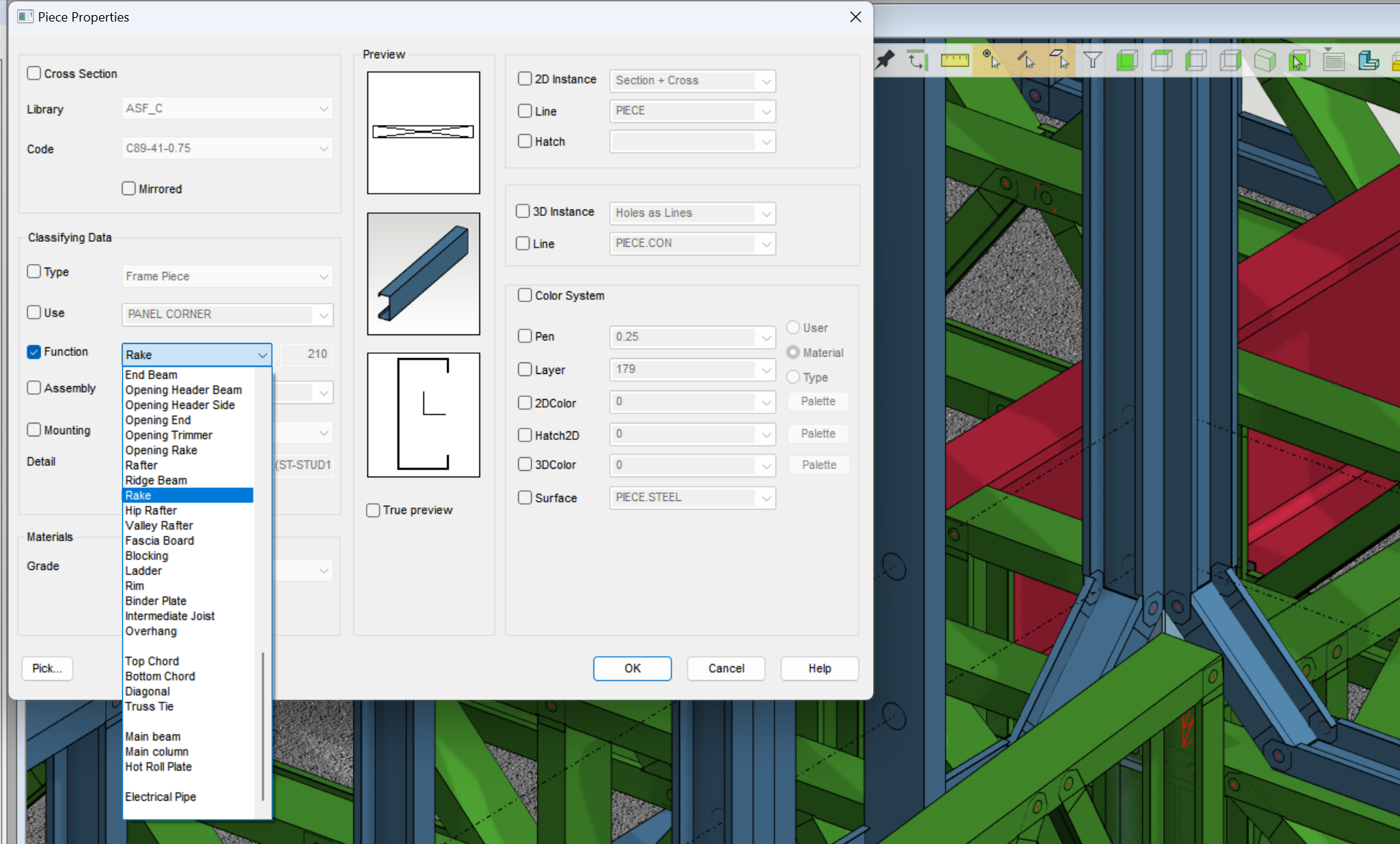
This error points at the member with function that is not recognised in wall engineering. For example, the 45-degree diagonals are in the load path but they are not recognised. To work around, user can change the piece function from diagonal to rake. They will then not be included in wall engineering after the change.
Error: Structure XXX does not exist in engineering table! (Load table name)
The system could not find the structure being engineered in the load table. Please check the load table and ensure valid lines of capacities are in place.
Error: XXX didn't pass the practical engineering tests!
The pieces with this error message did not pass capacity check. Check the result and analyse the reason for failure. Make adjustment and perform wall engineering again. If the system cannot find the structure in the load table, this error message will also appear along with the one above.