Buckling is a failure mode in engineering and it can occur when the structure is subjected to compressive stress. Buckling is characterized by a sudden sideways deflection of a structural member and leads to the instability of the structure. Buckling is the most common reason to cause instability for compression members. Capacity of the member is decreasing when the buckling length of the member increases.
Euler buckling
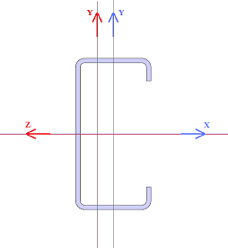
Euler buckling can happened over the both main cross-section axis. Buckling about section Z and section Y is shown in following picture.
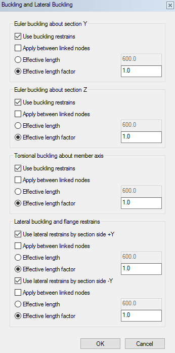
Effective length factor is 1.0 as default which means the buckling length is the same with geometrical length of the member. Choosing Apply between linked nodes function all additional nodes are taken care in the buckling length definition.
Effective length can be set also using absolute length value. This option is used when there are some secondary structures on the side of the frame which prevents the Euler buckling.
E.g. Battens are mounted into the main frame in 400 mm spacing, Euler buckling about section Y is 400 mm and about section Z the geometrical length.
Torsional buckling
In torsional buckling the member is twisting and the cross-section rotates from the original orientation. Effective length of torsional buckling can be reduced if the cross-section rotation is prevented.
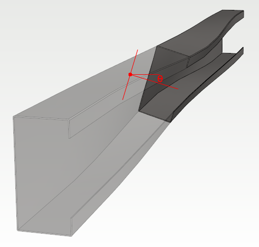
Lateral buckling
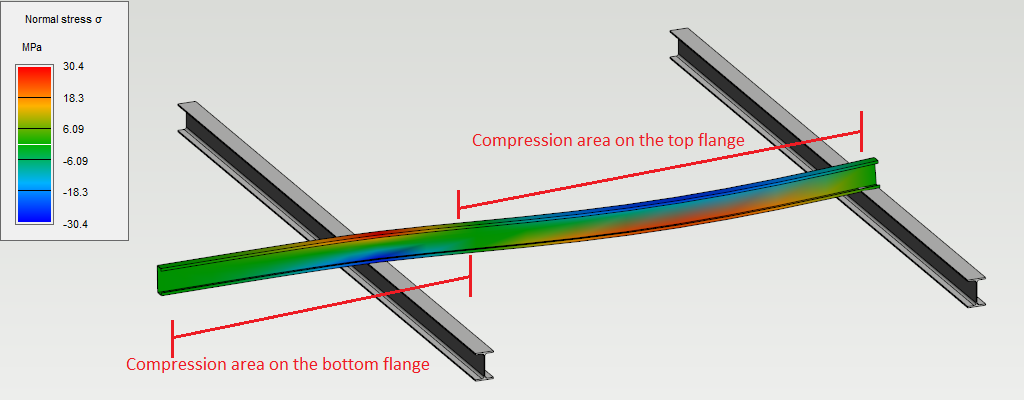
In lateral buckling flexural load increases to a critical limit and the beam will experience a lateral deflection of the compression flange of the profile. Lateral buckling can be avoided by supporting the compression flange of the profile in lateral direction.
Flange restrains are defined for both Y sides individually in lateral buckling. Positive direction is can be checked in part properties which shows the local origin point and positive directions. Check the profile orientation before setting buckling lengths.
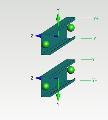
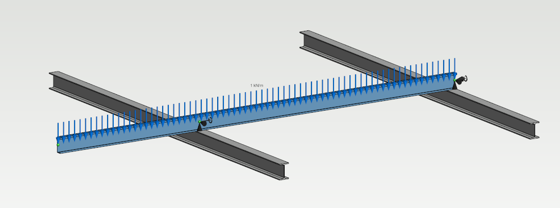
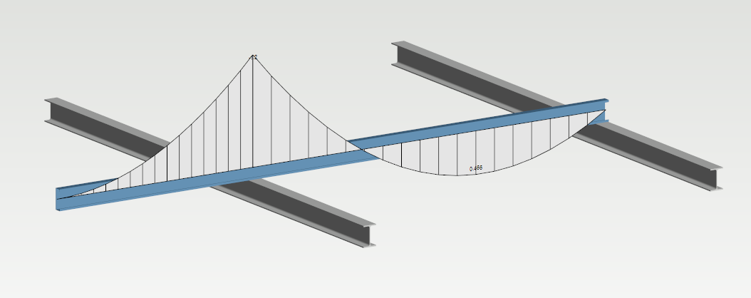
E.g. Linear loading in cantilever beam causes bending moment for both sides of the profile, the compression flange side changes along the beam. Supports for lateral buckling needs to be located in top or bottom flanges, depending the direction of the bending moment.