Back-to-back Truss Design in Vertex BD
Vertex has done research work to upgrade Vertex BD truss design functionality to meet back-to-back truss design requirements. Back-to-back trusses cannot be designed by using the same methods as in-plane trusses because of the asymmetrical structural system and non-linear elastic behavior of open CFS cross section profiles. Webs of back-to-back trusses are connected to chords with a lap connection and therefore it cannot be considered as a symmetrical structure with a middle plane of the truss structure. Evenly distributed external loading of asymmetrical chord cross section will also cause transverse stress to the truss structure and it must be taken into account in member and joint design.
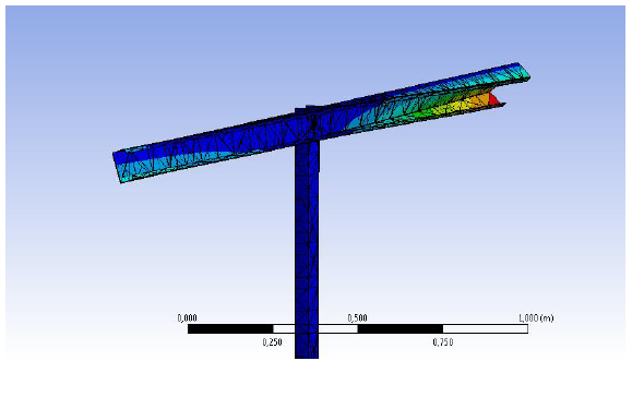
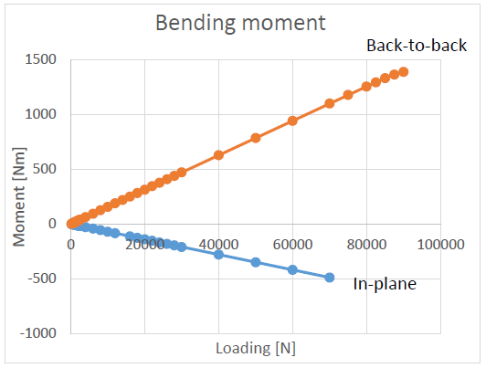
Without a proper inspection of truss stress members cannot be designed safely. In addition to the normal force, asymmetrical lap joint bends webs of the truss. Bending moment will reduce the capacity of the web and it must be taken into account in the member design. The situation is the same in the case of in-plane truss although the amount of the moment is smaller. Bending moment is caused by the eccentricity of the joint. We have verified the amount of the moment by using ANSYS finite element method software.
Without a proper inspection of truss stress members cannot be designed safely. In addition to the normal force, asymmetrical lap joint bends webs of the truss. Bending moment will reduce the capacity of the web and it must be taken into account in the member design. The situation is the same in the case of in-plane truss although the amount of the moment is smaller. Bending moment is caused by the eccentricity of the joint. We have verified the amount of the moment by using ANSYS finite element method software.
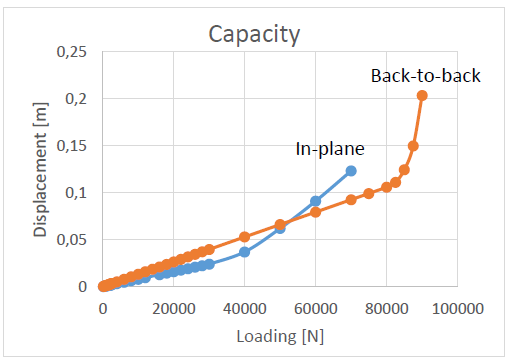
In the capacity chart, the displacement of the in-plane and back-to-back webs is displayed in respect of the loading. In the beginning of the test displacement of both webs is increasing linearly. The maximum capacity of the web can be considered to the point where displacement diverges from the linear behavior. According to the ANSYS tests the back-to-back web has greater capacity although the bending moment stress is also greater. That is explained by the direction of the bending.
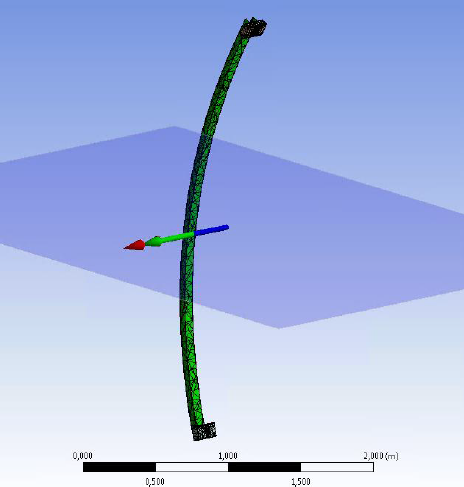
The behavior of top chord was also verified with ANSYS. Top chord of back-to-back truss bends around its shear center under loading. The shear center of C shaped profile is located outside the cross section. Loading is applied to the top flange when eccentricity of shear center cause torsion stress to the profile. According to the ANSYS test, cross section won’t twist around the shear center when the loading of top chord is applied through roof laths. In that case torsional stress is insignificant and it does not need to be taken into account in the member design.
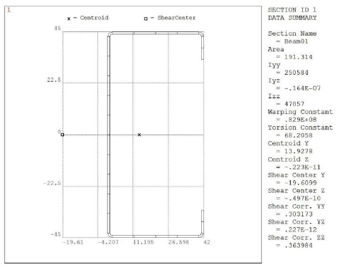
It is crucial for the Vertex BD truss design development to get further information about the back-to-back truss behavior under loading. Some other design software have not paid attention to the eccentricity of back-to-back trusses and therefore their calculation results may not be reliable. According to our research, eccentricity will have great effect on the behavior of back-to-back trussed and it will be taken into account in Vertex BD.
