
You can add a rectangular cross section directly to the profile library by entering the cross section dimensions. If the cross section is not rectangular, first draw the shape of the cross section.
Add a rectangular cross section
Select System | Libraries | Libraries. The library browser opens.
Open the folder Custom Libraries / Materials / Profiles.
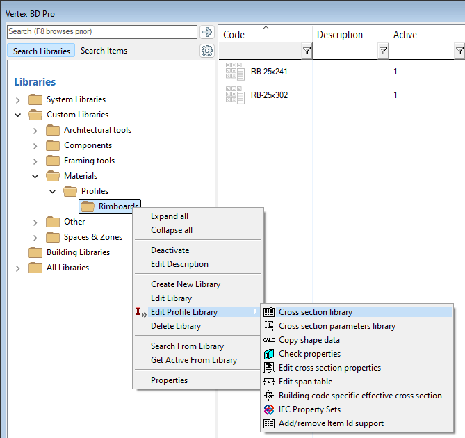
Choose the library to update.
Right-click and select either of the following:
-
Edit Library
-
Edit Profile Library > Cross section library
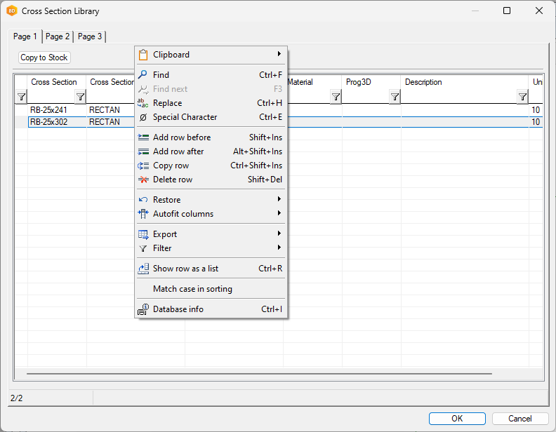
The Cross Section Library database view opens.
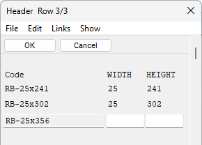
Add a new row to the database by copying an existing one. Move the cursor to the desired row, right-click and select Copy row.
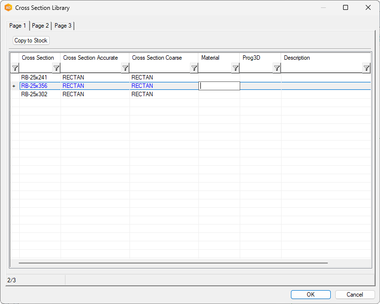
The new row is marked in blue color. Make changes on this row.
Fill the Cross Section field in Page 1 and check all the other pages and update profile values, if needed.
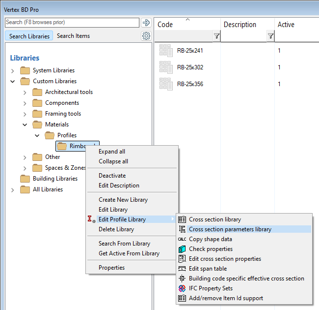
Update the parametric values of the profile to the cross section parameters library. Right-click the library in the left-hand browser pane and select Edit Profile Library > Cross section parameters library.
Fill empty values in the database view and click OK.
If you change an incorrect dimension or another profile property in the library, such as the profile weight, and you have already added the profile to the building, you must manually update the change to the profiles in the building.
-
Go to the 3D frame model.
-
On the Modeling tab, click Tools > Update Profiles from Library.
-
Click the profile or press Ctrl+A to select all profiles, and then Confirm.
Add a non-rectangular cross section
Each non-rectangular cross section size will have its own drawing (*.vxp).
The Cross Section Library might look something like this.
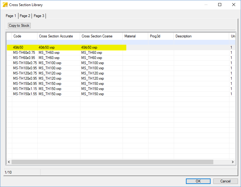
The highlighted row has been added, as above, but has been given a new name.
Note that in the example above, the same drawing file has been used for profiles with the same overall dimensions but different steel thicknesses. However, all drawings could just as easily be unique.
As mentioned, you will not enter any information into the Cross Section Parameters Library. Instead, in File Explorer, find the profile library.
For the above example, this is \custom\complibs\_proflib\HW_TOPHATS.
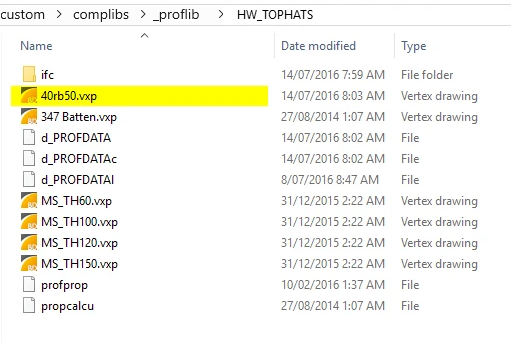
Copy one of the existing .vxp files and rename it to what you called it in the Cross Section Library.
Drag and drop the new .vxp file into Vertex. The cross section drawing will open. You can now edit it to the required dimensions.
You can just stretch everything, but you can also draw lines etc. if you want it to be very accurate. There are a couple of things to remember.
-
Make sure that the center of the profile is over the 0,0 cross mark. This is the insertion point used by Vertex.
-
The only thing that is absolutely necessary in the drawing is the hatch pattern. The hatch is what defines the profile, not the lines or polylines. If you delete it, make sure you put it back.
Learn more about drawing a cross section: Add a Drawn 2D Profile to the Library
Video
This video shows how to edit the cross section library in the previous user interface.
Related Articles