
In the previous steps, we defined the Default Details and the Floor Framing Detail Sets. In this step, we will look in detail at framing details.
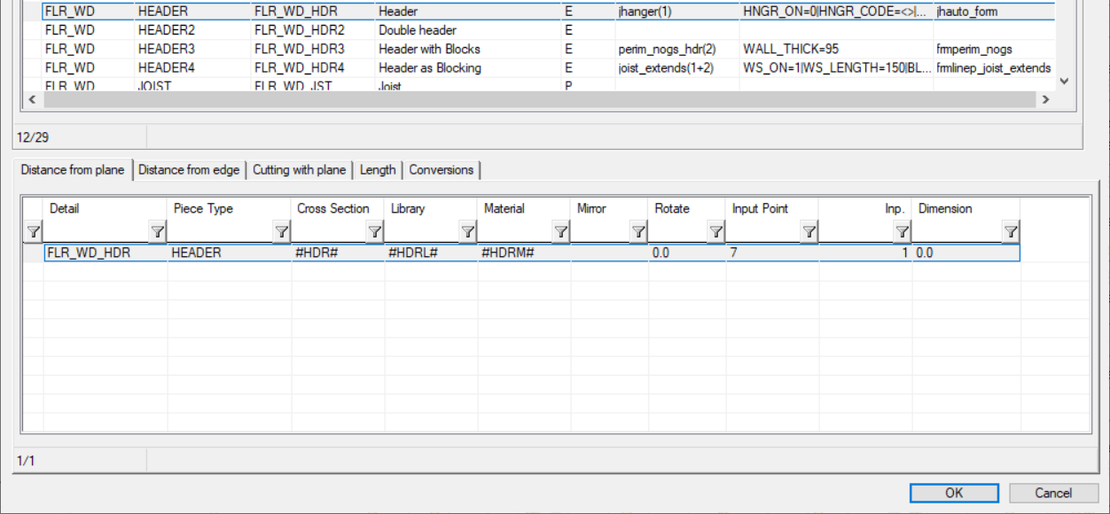
When you select a framing detail in the upper database view, the profiles created with the detail are updated in the lower database view.
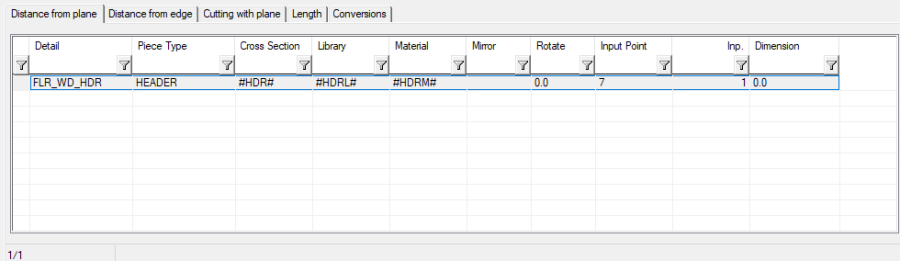
A framing detail can create as many profiles as you like. Each row in the lower database view represents one profile.
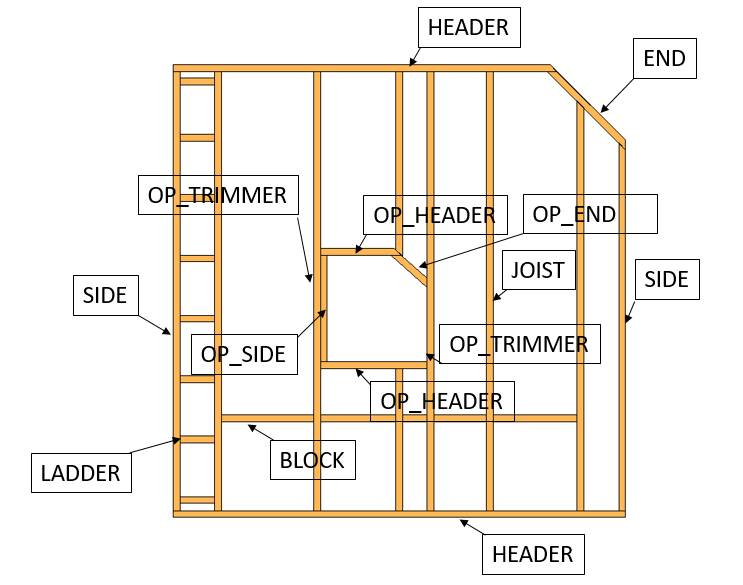
Piece Type
In this example, Piece Type is HEADER. The property Function in the profile properties refers to it.
In the case of BLOCKING, the piece will be automatically cut by the joists.
In the case of LADDER, the piece will automatically turn 90 degrees to the edge.
Cross Section
The values in the fields Cross Section, Library and Material have been defined as #HDR#, #HDRL# and #HDRM#. The system will look these values up from the Additional Parameters defined by the framing tool in use.
If the parameters are not found from the framing tool, it will use the default piece values defined in the framing tool.
You can also enter fixed values in the fields Cross Section, Library and Material. For example: 45x45, Wood, C24. In this case, the profile generated by the framing tool will be fixed and it cannot be changed by the user.
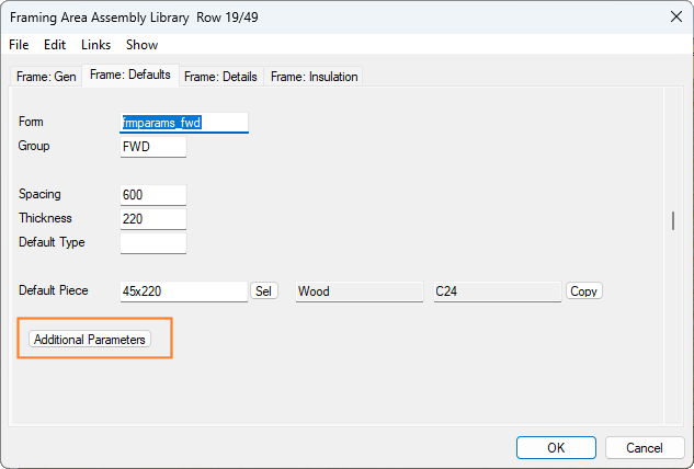
The Additional Parameters can be defined on the Frame: Defaults tab in the framing area assembly library.
Input Point
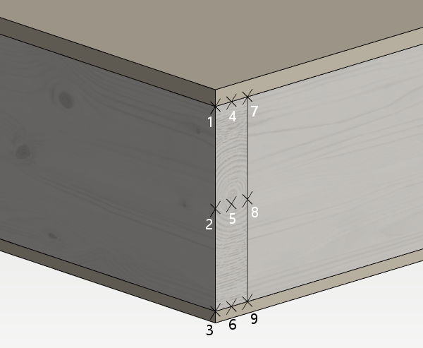
A piece can be positioned using one of nine reference points in the Input Point field. Mirroring and rotating are then done using that reference point.
Distance Perpendicular to the Plane
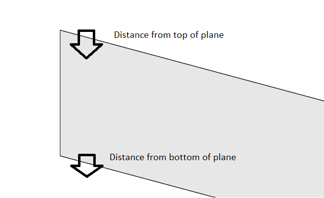
In the fields Inp. and Dimension on the Distance from plane tab, the distance of the piece from the top or bottom surface of the structure is determined.
You can use fixed numbers, for example 45, or you can use replacement texts to make the dimension parametric. For example:
-#SB:>HDR# will be replaced with the WIDTH of the section defined by #HDR#
-#SH:>HDR# will be replaced with the HEIGHT of the section defined by #HDR#
-#SF:>HDR# will be replaced with the FLANGE GAUGE of the section defined by #HDR#
-#SW:>HDR# will be replaced with the WEB GAUGE of the section defined by #HDR#
-#ST:>HDR# will be replaced with the GAUGE of the section defined by #HDR#
You can mix and match also, for example:
-#ST:>HDR#-1
Vertical Distance from the Plane
If you want to define vertical distance from a certain point in roof framing details, distance from reference point can be used for that purpose.
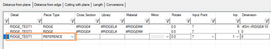
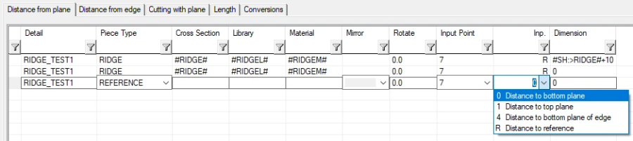
For the reference point, a row is added to the framing details database, and REFERENCE is selected as the Piece Type. This row just adds reference definition, not a profile at all.
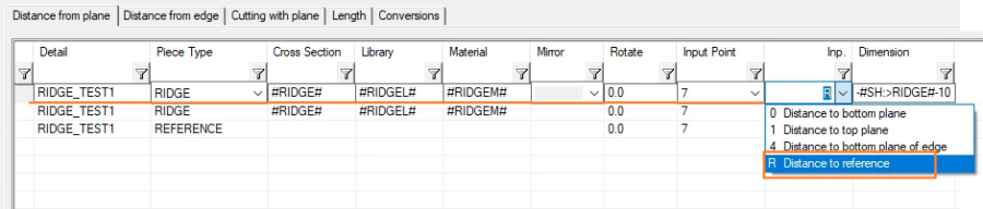
For the profile, select Distance to reference from the list in the Inp. field. This option is used to define a reference to where the profile position is measured. When a reference point is used as a measuring point, the distances are given in vertical direction. Otherwise, a perpendicular measurement is used from the selected plane of the structure.
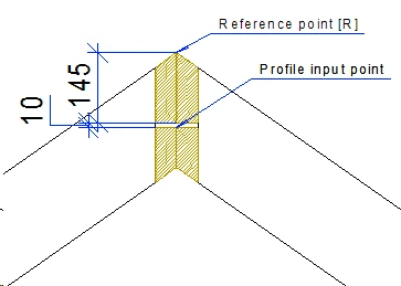
An example situation where this kind of detail can be used is below (notice that cutting of top and bottom of the profile can be defined on the Cutting with plane tab). Ridge profile size is 45x145. 10 mm cap is required between ridge profiles.
If you would like to setup reference point to be at the bottom surface of the structure, select the input point to be at the bottom for the REFERENCE itself:
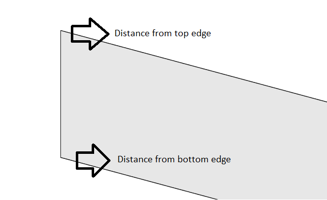
If you want to measure the reference point (vertical distance) from a certain edge, you can define the distance from the edge on the Distance from Edge tab.
Distance from Edge
On the Distance from edge tab, the distance of the piece from the edge is determined.
You can use fixed numbers, for example 45, or you can use replacement texts to make the dimension parametric. For example:
-#SB:>HDR# will be replaced with the WIDTH of the section defined by #HDR#
-#SH:>HDR# will be replaced with the HEIGHT of the section defined by #HDR#
-#SF:>HDR# will be replaced with the FLANGE GAUGE of the section defined by #HDR#
-#SW:>HDR# will be replaced with the WEB GAUGE of the section defined by #HDR#
-#ST:>HDR# will be replaced with the GAUGE of the section defined by #HDR#
You can mix and match also, for example:
-#ST:>HDR#-1
If you are using a REFERENCE piece type for defining a vertical distance for a profile, and want to set a certain distance from the edge, the refecence point (vertical distance) is measured from certain distance from edge, you can setup distance from edge in next tab.
Joint ID
Every piece in every detail has a Joint ID. These IDs are linked together to form a connection, for example trimmed to a plane or to use an ADT style connection like a light gauge steel joint. More information about Joint IDs can be found here Floor Framing Joint Connection Types.