
In the previous step, we defined the default or standard details, see Default Details. In this step, we will define framing details.
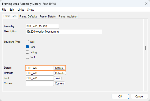
Click the Details button on the Frame:Gen tab to open the Detail Set and Framing Details databases.
Note that the set in the example figure is FLR_WD so it will open the FLR_WD detail set. If the value was FLR_ST, it would open the FLR_ST set. You can have as many sets as you like, though it is easier to use and create new details to the default sets.
You will now see this page:
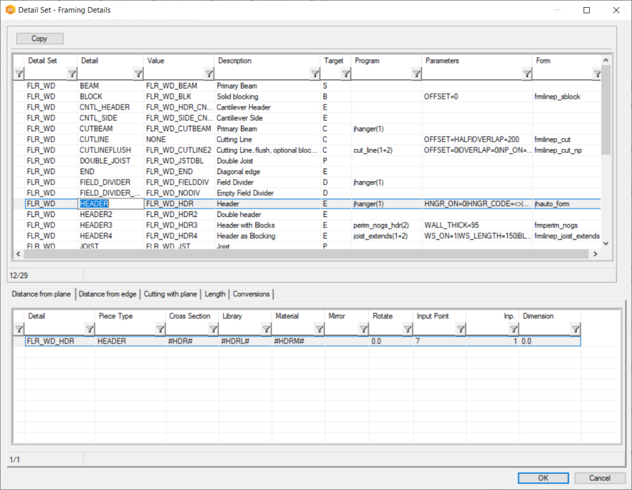
The columns are as follows:
-
Detail Set, for example FLR_WD. The group of framing details related to timber floor framing.
-
Detail, for example HEADER. The name of the detail which is used in the detail file on the previous page.
default= HEADER HEADERIf you wanted to make HEADER2 the default header, you can edit the FLR_WD file like this:
default= HEADER HEADER2 -
Value, for example FLR_WD_HDR. A unique name for the detail.
-
Description, for example Header. A user-friendly description of the detail.
-
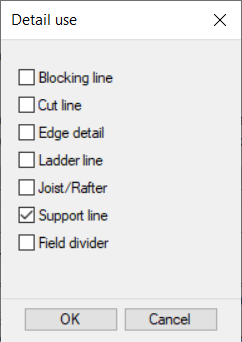
Target, for example edge detail or blocking line. These options enable/disable details for selection when adding framing detail lines and framing splits. You can tick multiple choices, if the detail can be used as an edge line and support line, for example.
The following columns are more advanced options:
-
Program, for example jhanger(1). An ADT file can be run for the edge detail, for example adding a joist hanger between joists and the header, or changing a piece to another piece based on some parameters.
-
Parameters, for example (all parameters in one row):
HNGR_ON=0|HNGR_CODE=<>|HNGR_LIB=HANGER_SYS|
HNGR_HNAIL=0|HNGR_JNAIL=0|
HNGR_PSS=0|HNGR_PSS_LEN=300|
HNGR_STF_END=0|HNGR_STF_LEN=150
|HNGR_FREE=0|HNGR_LOOSE=0|
HNGR_LIB_DESC=Hangers, System Library|
Parameters to the ADT program. The parameters are split by the vertical bar ( | ). -
Form, for example jh_auto_form. When editing an edge in the floorplan or model the user can press a Parameters button. The defined form file will be used, and the form file will use the parameters defined above.
Next, in Floor Framing Details, we will look in detail at framing details.