
Open the Framing Area Assembly library for editing by selecting System | Structural Libraries | Floor and Roof Framing.
Move to the desired row on the database view by pressing the Arrow Down key or select Show > Browse to view the row list and then select the desired row.
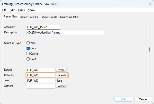
The Defaults file and button on the Frame: Gen tab is for defining the standard details around the structure, for example floor and roof, including the header, sides, and parts around the openings. In the field (white box) you can enter the name of the file, which can be found in the “custom/details” or “system/details/” folder. The file is a text file. The file can be opened by pressing the Defaults button. Typical file examples are FLR_WD for floors, BATTEN_WD for wall batten layers, ROOF_WD for roofs. There are matching files for light gauge steel structures using the ST suffix, for example FLOOR_ST. You can create your own details file by simply copying the file in Windows File Explorer and giving it a name, for example MY_FLR_WD. If no details file is given, the system will use its own internal defaults.
Here is the BATTEN_WD detail file.
!*******************************************************************************
! BATTEN_WD    / 2012-05-14 / Vertex Systems
!
! Default details for batten layer
!*******************************************************************************
!
default= PIECE     JOIST
default= OP_GAP~95-119   OP_GAP1
default= OP_GAP~120-139  OP_GAP2
default= "OP_SIDE~PUNCHTYPE = HATCH" NONE
default= OP_SIDE   OP_TRIMMER
default= OP_HEADER OP_HEADER
default= HEADER NONE
default= HEADER_TOP HEADER_TOP
default= HEADER_BOT HEADER_BOT
default= OP_HEADER_TOP OP_HEADER_TOP
default= OP_HEADER_BOT OP_HEADER_BOT
default= SIDE SIDE
default= END END
default= BACKER_LB NONE
default= BACKER_NB NONE
complete_prog= ADD_BRACKETS.prg
The details in the file are defined using the following formats:
default= XXXXX YYYYY
-
XXXXX is the name of the internal edge detail
-
YYYYY is a detail from the Framing Details database
default= “XXXXX~PARAMETER = VALUE” YYYYY
-
XXXXX is the name of the internal edge detail
-
~PARAMETER = VALUE is a parameter from the hatch/shaft component
-
YYYYY is a detail from the Framing Details database
complete_prog=    XXXXX
complete_prog=    YYYYY
-
XXXX and YYYYY are the names of ADT program files which would be found in custom/macros/sfrmconn folder, which allows for post detailing, for example adding I Clips between joists. Complete programs are optional.
The writing of ADT programs is an advanced topic not covered by this guide. Your local Vertex office can create these at a customization cost.
In the next part of this guide, Floor Framing Detail Sets, we will look at how framing details are defined.