|
Click Here to go to Quick steps of Truss Engineering Process in more details |
|---|
We can check the design of the roof with the engineering module of Vertex. To do that ‘Internal load Pressure Area’ and ‘Wind Loads’ need to be defined.
1. Generate/define 'Internal Pressure Area' (in 2D Ceiling model pair):
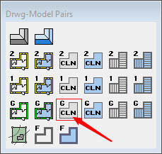
Switch to ground floor Ceiling Model pair :
-
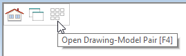
First we need to change to ceiling model pair, to do that we need to activate Drawing Model pair menu.
-
OR by pressing F4 key.
-
Press F2 to switch between 2D and 3D view
-
In 2D view of 'Ground Floor Ceiling’ pair, you may have the Ground Floor Walls as reference in it. We can turn off the reference file/s if needed.
-
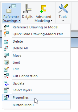
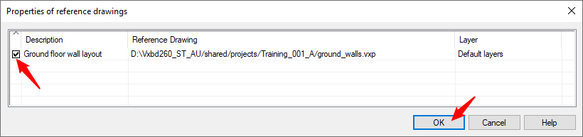
In modelling tab, go to ‘Reference Drawings’ and from the drop-down list click on ‘Properties'.
-
Untick the box for the Ground Floor Wall layout reference drawing.
-
OR
-
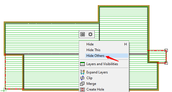
If you have set the visibility of Ground Floor Walls in ‘Ground Floor Ceiling’ model pair. You can select the ceiling/s plane. Right click and from the contextual menu click on 'Hide Others'
-
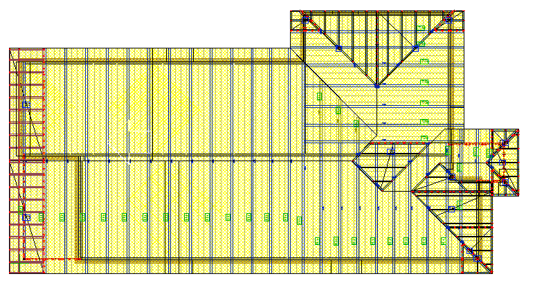
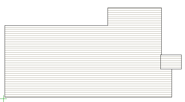
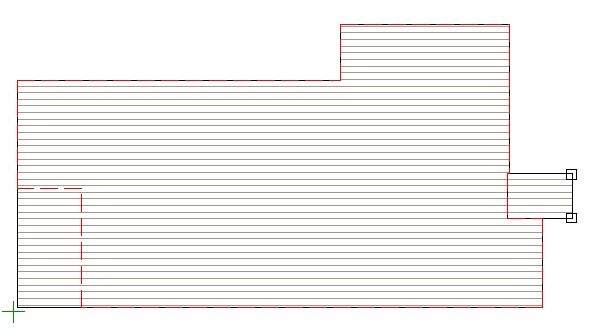
Now you should have plan view of the ceiling, something like this.
Define 'Internal Pressure Area':
-
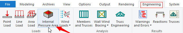
To define building 'Internal Pressure Area' go to ‘Engineering’ tab. Click on ‘Internal Pressure Area’.
-
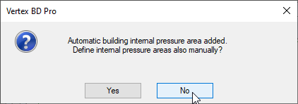
When you get the message dialog box, you can either select 'Yes' ( if you want to define internal pressure area manually ) OR click ‘NO' to continue, this will automatically determine the Ceiling Internal Pressure Area.
-
There is no need to manually select any additional areas for this exercise.
-
So click NO in the dialog box.
For Vertex to determine automatic building internal pressure area, there shouldn't be any cut in perimeter walls of the building.
-
The Internal pressure area is indicated by the red dotted line as shown.
2. Generate/define wind loads for Ceiling (and any other special loads):
-
It will generate the wind loads for ceiling.
-
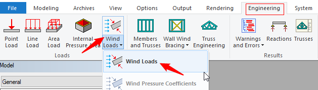
To define ceiling load go to ‘Engineering’ tab, → ‘Wind loads’ and form pull down menu select ‘Wind Loads’ to generate wind loads for ceiling.
-
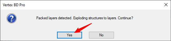
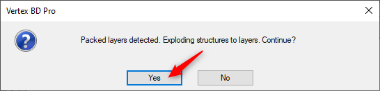
The message simply means that Vertex wants to break up the Ceiling into separate entities, so it can define a surface, to apply wind loads on. Preselected ceiling type might include ceiling, ceiling battens and sheeting.
-
To create the correct size envelope for the roof structure, vertex only use single surface to do the engineering calculations. No changes are actually made to the model.
-
In the dialog box click on 'Yes'.
For roof truss engineering purpose, it is imperative to have a sheeting layer below ceiling plane to take the ceiling loads layer on it.
-
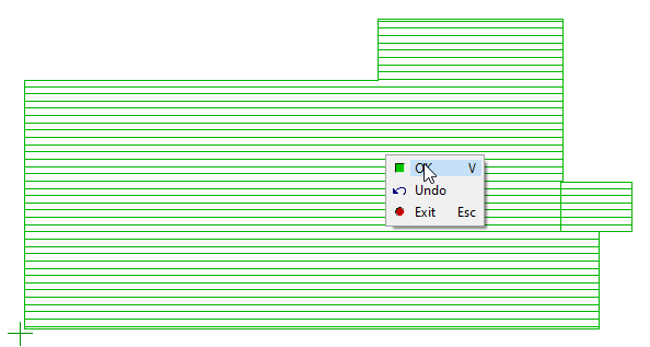
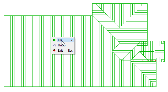
Vertex prompts to 'select the area'. So Select the ceiling/s. Right click and click on OK to confirm OR press ‘V’ to confirm
-
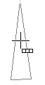
Vertex prompts to place the arrow ( as shown ) to indicate the prevailing / main wind direction. ( First time only )
-
You can position the arrow and rotate it ( if needed ) by using the arrow keys on the keyboard
|
Click Here to refer to Wind Load help for Vertex truss design |
|---|
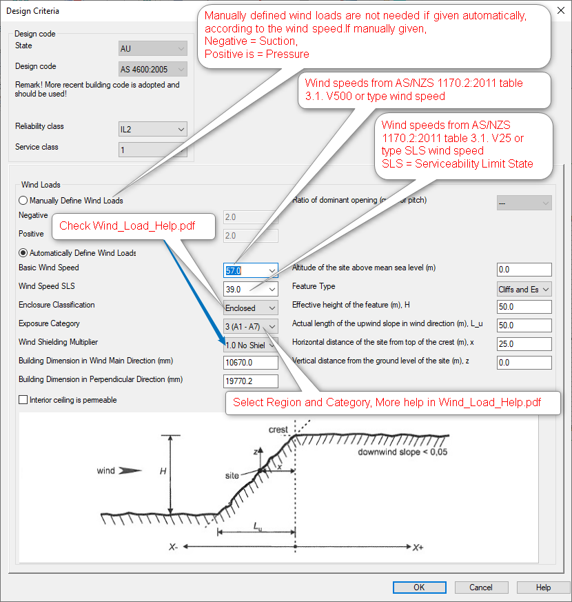
Design Criteria Description :
|
|
|---|
-
Building Dimension in Wind Main Direction (mm) are extracted by Vertex from the model.
-
Building Dimension in Perpendicular Direction (mm) are extracted by Vertex from the model.
-
If enclosure value is not available use ‘Enclosed’ in regions A and B and ‘Dominant Opening Ratio below 1’ in regions C and D.
All these figures must be input in meters (m).
|
|---|
-
Interior ceiling permeable: means internal pressure area will be added to Bottom chord.
-
If you Tick ON 'Interior ceiling permeable': means internal pressure area will be added to Top Chord instead of bottom Chord of the truss.
-
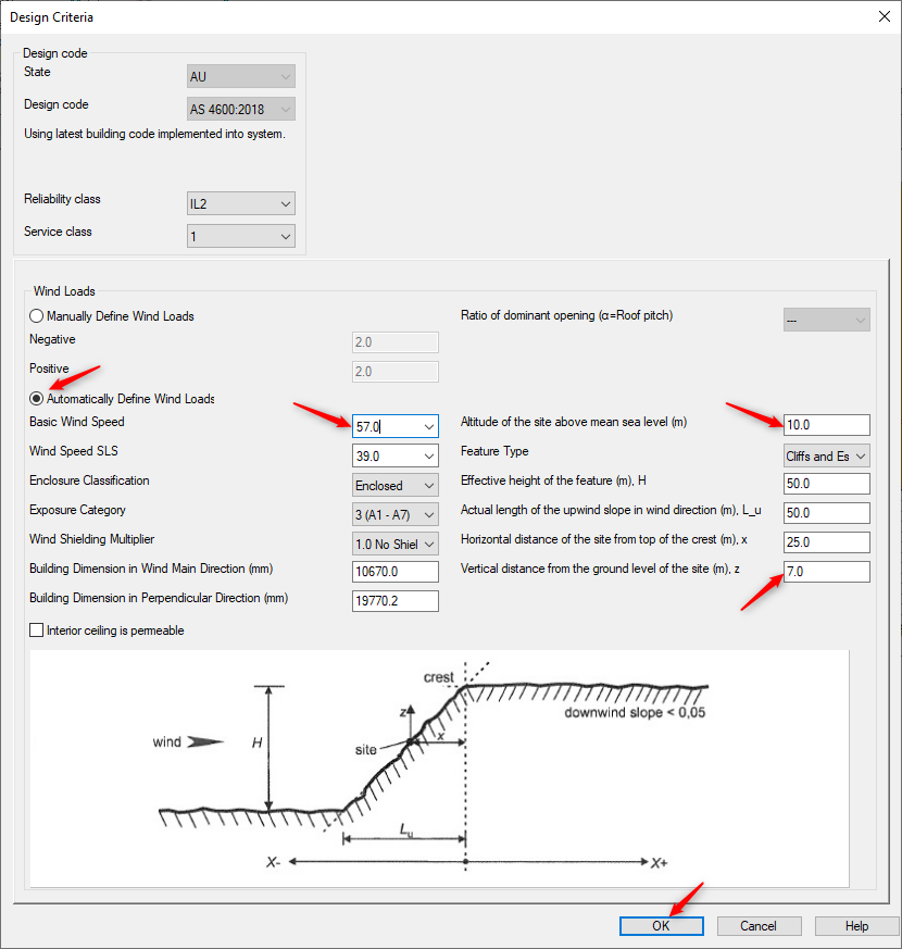
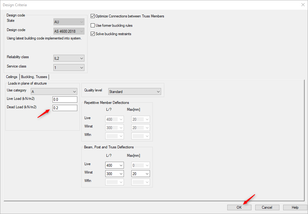
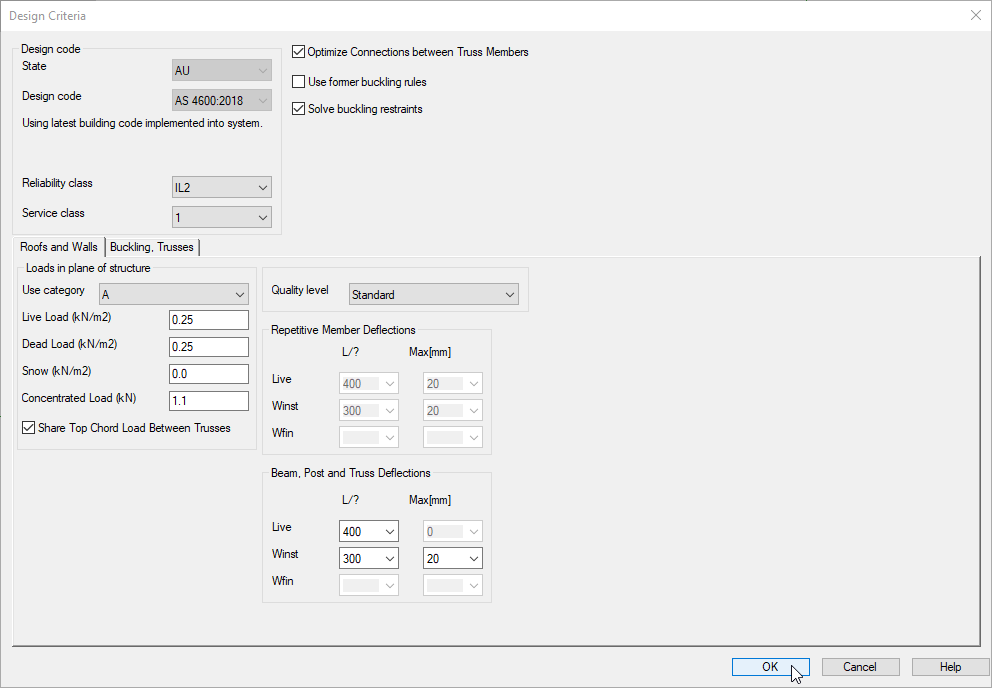
You can define the Design Criteria in this dialog box.
-
Click on ‘Automatically Define Wind Loads’ that will activate 2 fields below.
-
Fill out the ‘Basic Wind Speed’, ‘Wind Speed SLS’ and ‘Exposure Category’ as shown in the screen shot and click on OK
-
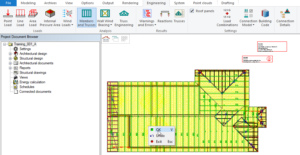
Vertex will now generate the loadings on the ceiling structure.
-
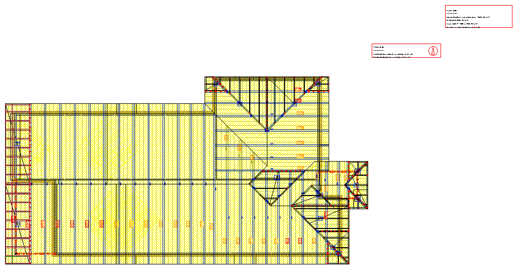
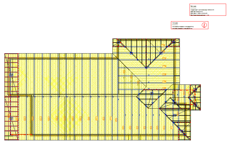
Ceiling load have been added. Now you should have a view that looks something like this
-
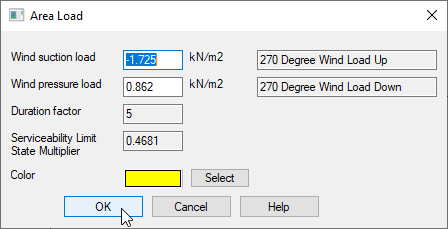
If you double click the ‘yellow’ area, it will display the Area loads.
-
Different area may have different area loads
3. Run ‘Members and Trusses’ analysis on the ceiling:
-
It will analyze the strength of the truss structure
-
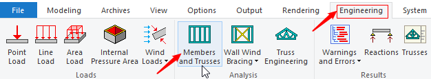
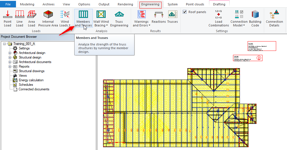
While you are in 'Ceiling' model pair, go to ‘Engineering’ tab, Click on 'Members and Trusses'
-
Vertex will load the building design codes.
-
In the Design Criteria dialog box you can accept the settings for the ceiling ‘Dead Load’ as 0.2 kN/m2 or change to suit. 10mm plaster board direct fixed is closer to 0.1kN/m2 and if there is insulation and battens, it might be 0.15kN/m2
-
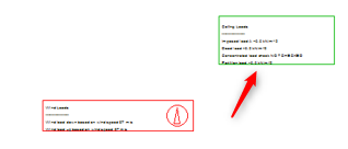
Vertex will run engineering check ( the Ceiling Loading will be calculated ) and the results will be displayed in a text box in the view which can be positioned near the structure.
-
Right click and confirm or press V to confirm
-
Ceiling Loads' box lines around the design results should turn green.
-
This means that ceiling design pass the design checks
4. Generate/define wind loads for Roof ( In 2D Roof model pair ):
Switch to Roof Model pair :
-
We will now define and apply loads to the roof.
-
Use F4 to open up the Roof model pair menu in 2D view and turn off the reference drawing as we have done previously in ceiling model pair.
-
To define wind Loads for Roof, go to ‘Engineering’ tab, → ‘Wind loads’ and form pull down menu select generate ‘Wind Loads’.
-
The message simply means that Vertex wants to break up the roof into separate entities, so it can define a surface, to apply roof wind loads on.
-
The preselected roof type might include roof, battens, sheet / tiles.
-
To create the correct size envelope for the roof structure, vertex only use single surface to do the engineering calculations. No changes are actually made to the model.
-
In the dialog box click on yes
-
Select all roof planes ( hold down the Ctrl key ), right click and click on OK to confirm OR press ‘V’ to confirm.
-
When the ‘Design Criteria’ dialog box appears, fill it out the same as for the ceiling wind loads.
-
Remember to check that the Design Criteria Default settings are correct as well and then click on OK. Vertex will generate the wind loadings.

-
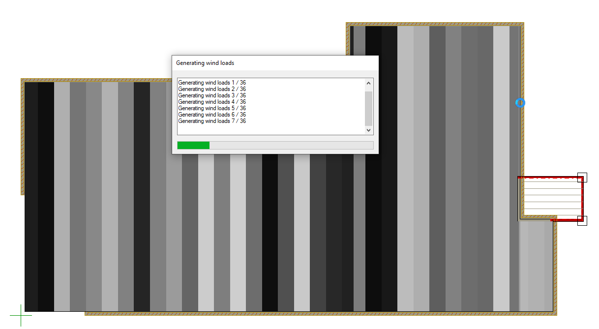
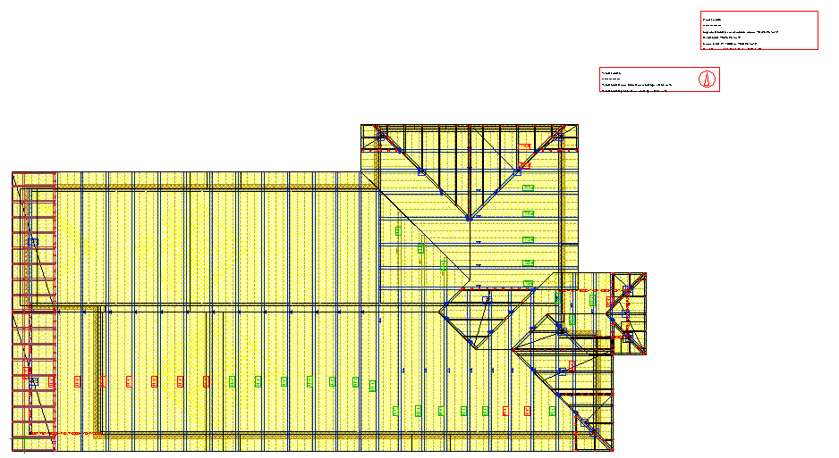
As Vertex processes the wind load, the screen will appear something like this image shown to the right
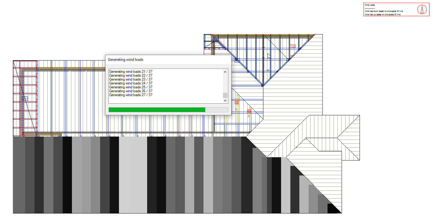
-
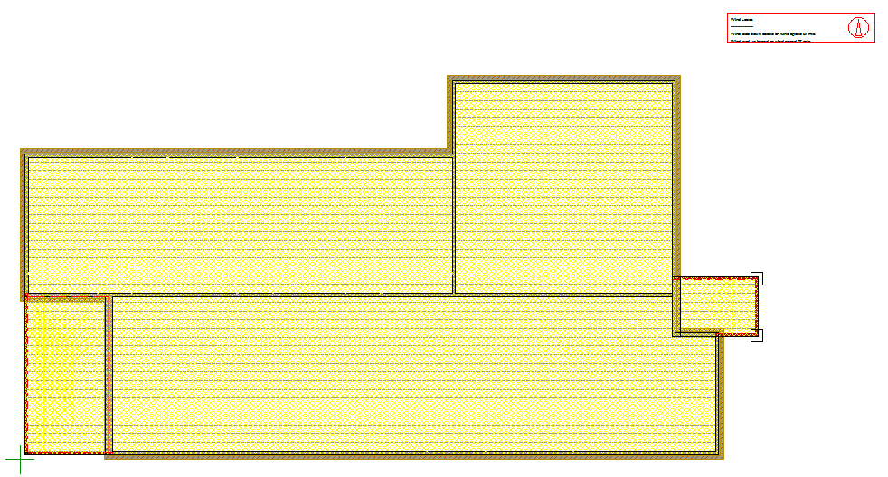
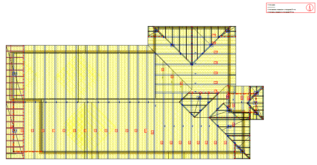
Roof load have been added. Now you should have a view that looks something like this
-
If you double click the ‘yellow’ area, it will display the Area loads.
-
Different area may have different area loads
5. Run ‘Members and Trusses’ analysis for all roof members and trusses:
-
While you are in 'Roof' model pair, go to ‘Engineering’ tab, Click on 'Members and Trusses'
-
Vertex checks for any structural arrangement issues in the model.
-
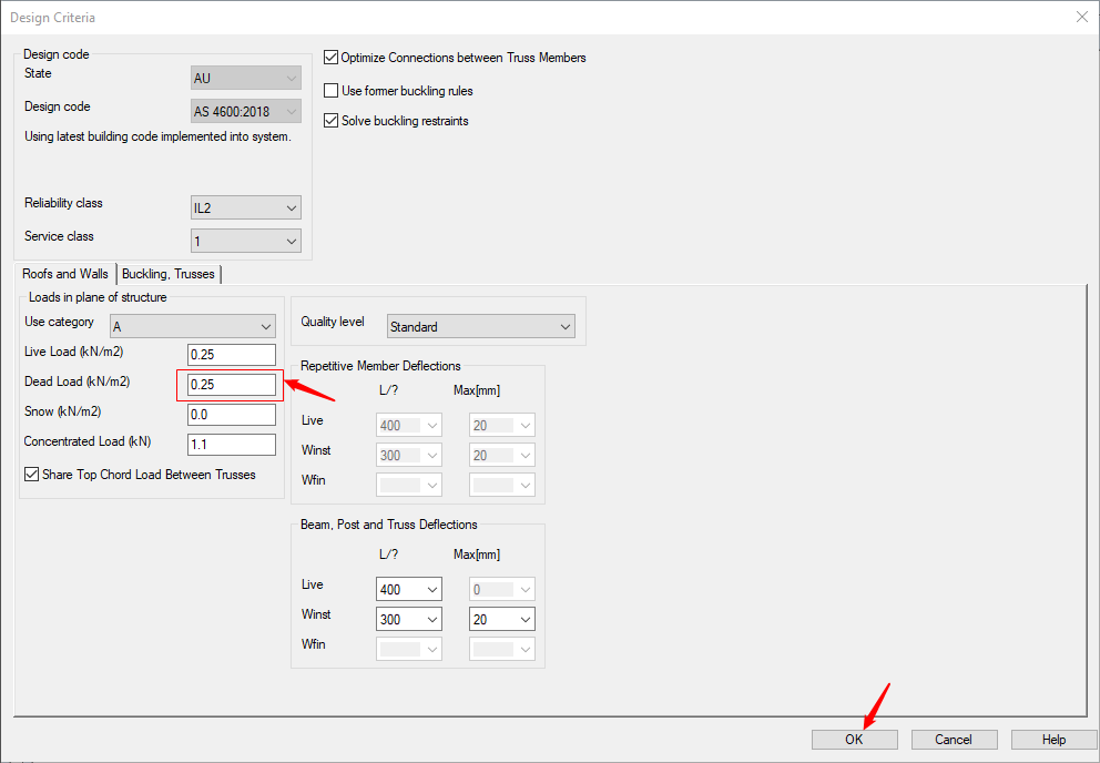
Now the design criteria dialog box opens.
-
You can change the ‘Dead Load (kN.M2)’ field to suit sheet metal roof or a tiled roof. ( for more detail of imposed action, refer to AS/NZS 1170.1:2002 Table 3.2 and Notes 3)
-
A sheet roof would be closer to 0.06kN/m2. This value should include the roofing material, battens, sarking and insulation etc.
-
Now vertex prompts you to 'Select object to design'
-
Select all trusses. ( select one truss first and then press Ctrl A key to select all trusses ) right click and click on OK to confirm
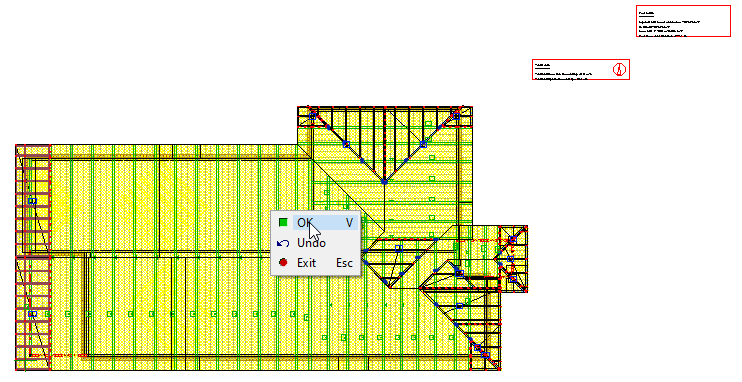
-
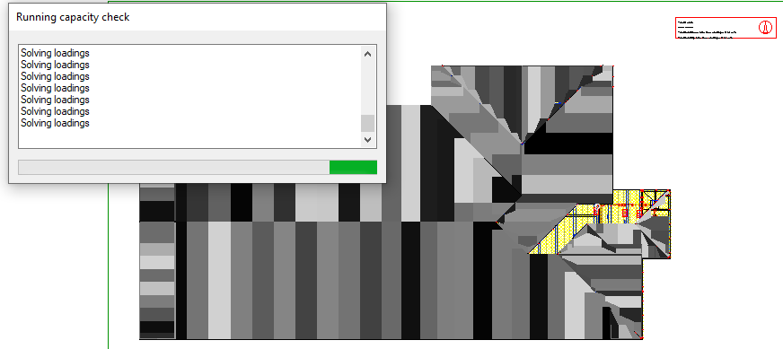
Vertex will run capacity check and solve loadings: means Vertex will check all trusses structure parameters and design criteria.
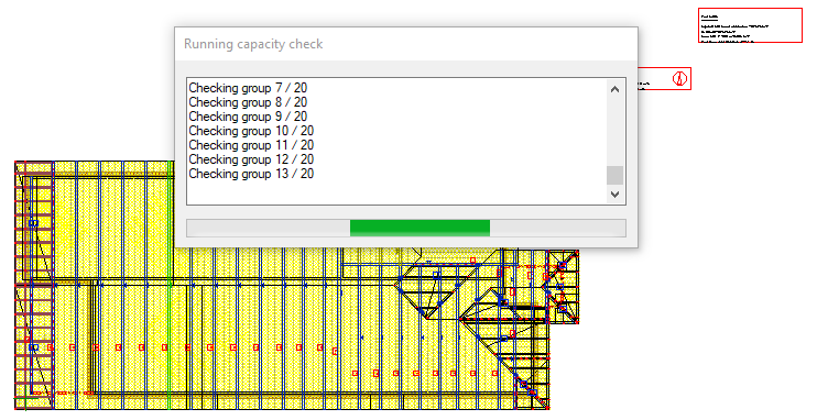
-
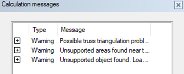
Once done, you will get message box on the left side of the screen ( in vertex window ) with Calculation messages.
-
Click on 'Close' at the bottom left of the 'Calculation messages box' or right click anywhere on the screen and click on OK
-
Vertex will take time to save engineering calculations.
-
Trusses that pass (all the structure parameters and design criteria), labels for those trusses will turn Green.
-
Failed trusses label will turn Red.
-
Failed trusses have to be engineered individually to eliminate error/s.
If trusses pass, all structure parameters and design criteria straight way ( first time ) then press ‘V’ to confirm. Now you will notice that roof loads result box will turn Green
-
You can go to 'Engineering' tab → Warnings and Errors and click on 'Warnings and Errors' to open the the warnings and errors message box
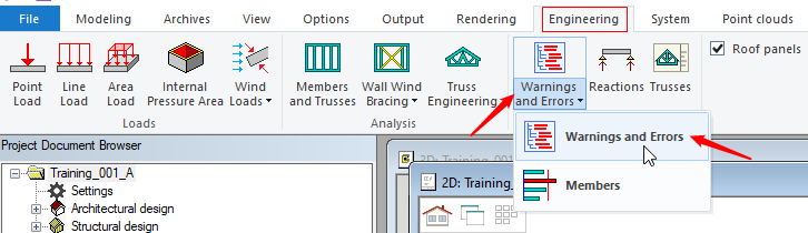
-
‘Warning’ message is something that Vertex thinks should be investigated but not necessarily a problem with the design.
-
‘Error’ message is a design issue that needs to be resolved.
-
All warnings and errors can be individually clicked and full message can be read at the bottom left hand side of the screen ( in Vertex Window ).
-
If you click on individual ‘error’ location will be displayed in both 2D and in 3D by a flashing arrow.
-
Now we will run through some of the typical issues which are commonly encountered at this point and which will prevent you from proceeding past this point in the engineering phase.
-
Once all the errors are resolved, again run 'Members and Trusses'. Vertex will take its time to calculate the structural arrangements. When done, the screen come to a halt, that is when you need to Select all the trusses (by holding down ‘ctrl’ ‘A‘) and press ‘V’ to confirm.
6. Run ‘Truss engineering’ for individual trusses that have failed (RED Labels):
-
In single / one ‘Truss engineering’ you can solve critical truss engineering situations quicker.
-
The functionality under one 'Truss Engineering' tab, enables fast structural changes such as adding / removing web pairs, adding side reinforcement to strengthen top/bottom chord without changing loads and supports and without regenerating parts for the truss.
-
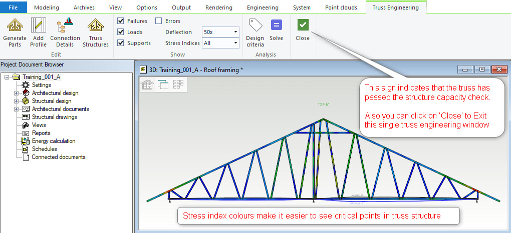
Locate critical engineering spots through stress index gradient colors, makes it easier to see critical points in the the truss structure.
-
Truss profiles can be modified interactively. The truss parts can be regenerated using 'Truss structure' rules to modify/optimize truss.
-
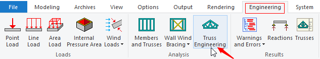
Go to ‘Engineering’ tab → ’Truss Engineering’ and select the truss (that you want to eliminate the error/s in )
OR
-
Select the truss, right click and form the contextual menu click on ‘Truss Engineering’
-
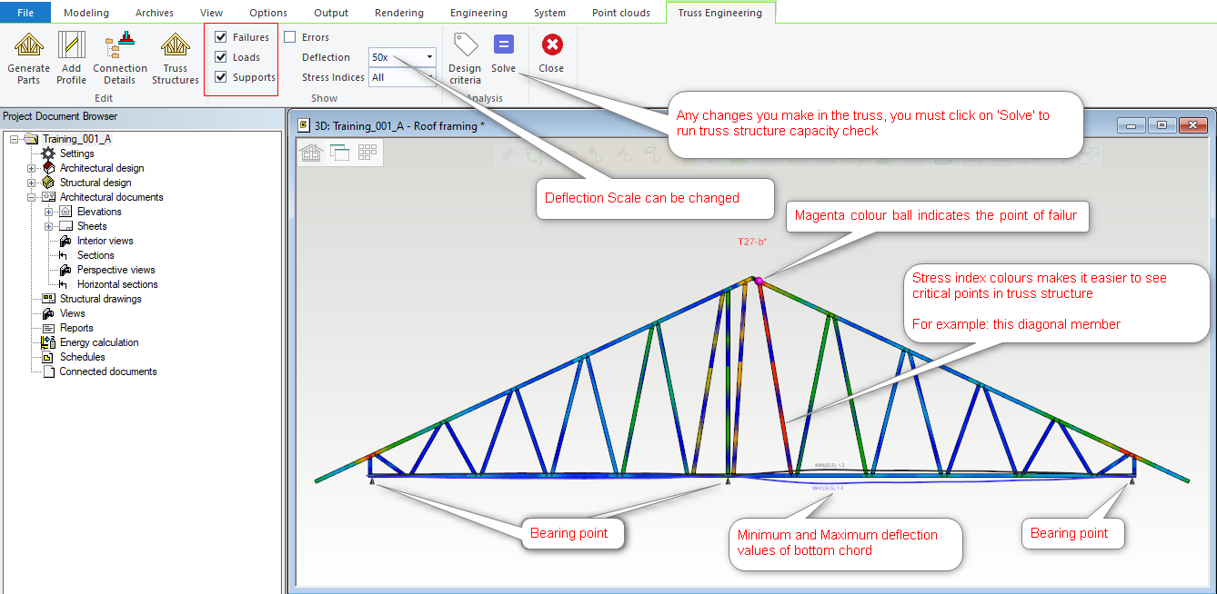
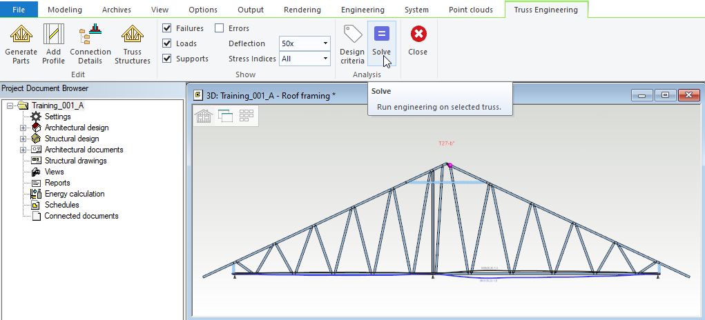
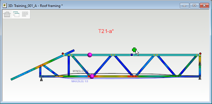
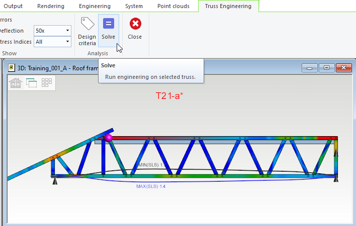
This will activate 'Truss Engineering' tab and opens a new window ( as shown below ). This window will display the truss with all the loads and supports and will indicate a magenta color ball to indicate the point of failure. This single truss engineering window also displays Minimum and Maximum deflection values of the bottom chord.
-
Stress index is now shown in gradient colors within single truss engineering window . This makes it easier to see critical points in the truss structure.
-
You can Select this

-
You can deselect this

-
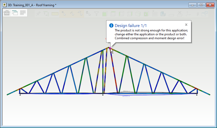
If you hover your cursor over the Magenta ball ( the point of failure ), it will display the error description.
-
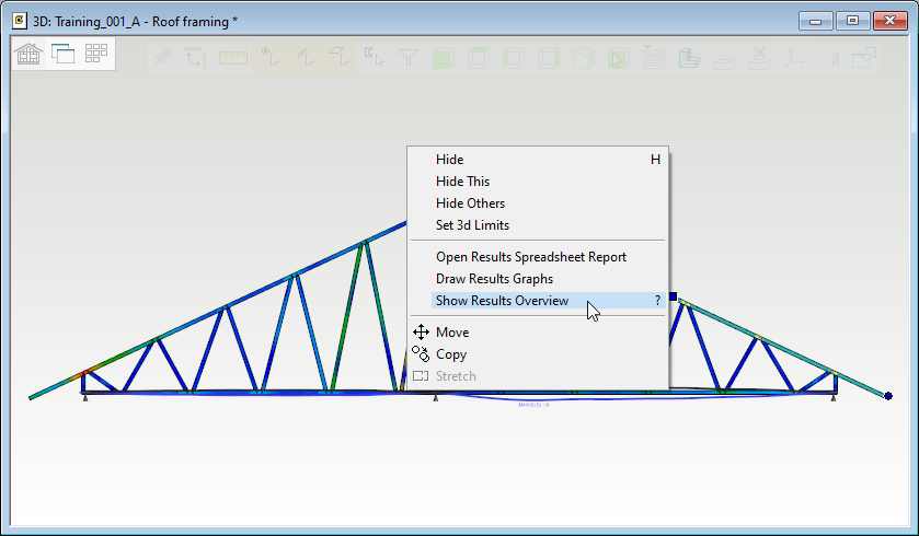
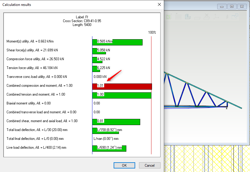
If you select the top chord ( that have an error on ). right click and from the contextual menu click on 'Show Result Overview'. it will display the calculation result of the prelselected length and error will be displayed with red color strip.
-
Since we can see the reason and the point of failure as well as stress index colours also shows critical points in that diagonal member, it is going to be easy to fix this error. To strengthen the members we can add a 'Tie', that will be offset from the top of truss by 400 mm . Which means we need to regenerate this truss parts ( in this one truss engineering window )
-
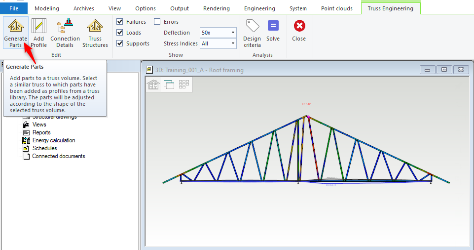
Click on 'Generate parts'.
-
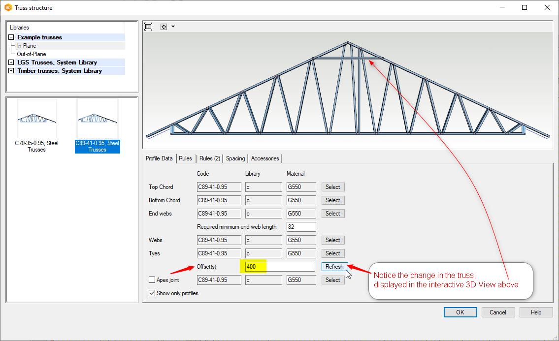
'Truss structure' dialog box opens up. In the first 'Profile Data' tab go to Offset(s) field type 400 ( this will add a 'Tie' that will be offset from the top of truss by 400 mm ).
-
Click on 'Refresh' and you will immediately see the change displayed (as shown in the image) in the interactive 3D window
-
Click on OK
-
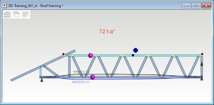
Notice that the 'Tie' have been added to the truss.
-
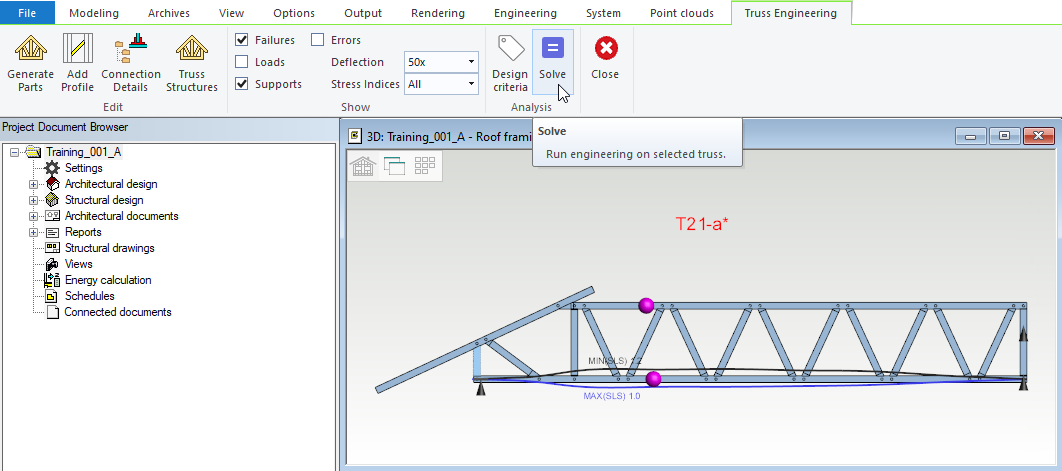
Now click on 'Solve' to run the structure capacity check.
-
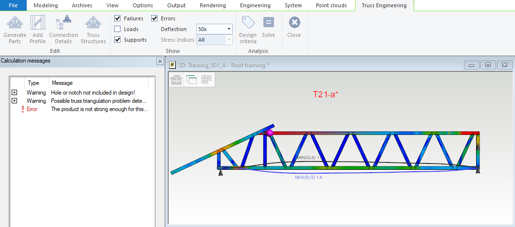
If the truss structure capacity check fails. The Error message will be displayed to the left in vertex window. In that case only after closing the error message, further action can be taken such as add/removing web pairs, adding side reinforcement etc. For more details refer to edit truss tips
-
Side reinforcement can also be used to strengthen the bottom chord of truss ( especially when there is a long span and or with low roof pitch ) as well as to strengthen top chord ( especially with long overhang ).
-
If you select any member ( especially the member that is failing either of these top chord, bottom chord, tie and diagonal web ) of the truss, right click and from the contextual menu click on 'Show Results Overview' it will display calculation results in a box with graph. Which can be helpful to pinpoint the error and hence further course of action can be determined.
-
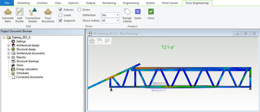
As you can see that the truss has passed the structure capacity check.
-
You can see the Stress index is now shown in gradient colors, which makes it easier to see critical points in the truss structure.
-
If you hover over any member ( top chord, bottom chord, tie, diagonal web ) of the truss, it will display calculation result.
-
Capacity summary result can be seen by right clicking ( anywhere on the one truss window ) and from the contextual menu select 'Capacity Summary Result'. The excel report will be displayed on the screen and can be saved for future reference.
-
Click on 'Close' to exit one truss engineering window.
-
Make sure to 'Save' the model every time you exit one truss engineering window. Otherwise, when you are in one truss engineering window for the next truss, vertex might freeze to save the previous changes, especially if you want to regenerate parts.
-
As you exit one truss engineering window and come back to roof model pair you will notice the trusses that had already passed, the labels for those trusses will now turn Orange.
-
Select the truss, right click and form the contextual menu click on ‘Truss Engineering’
-
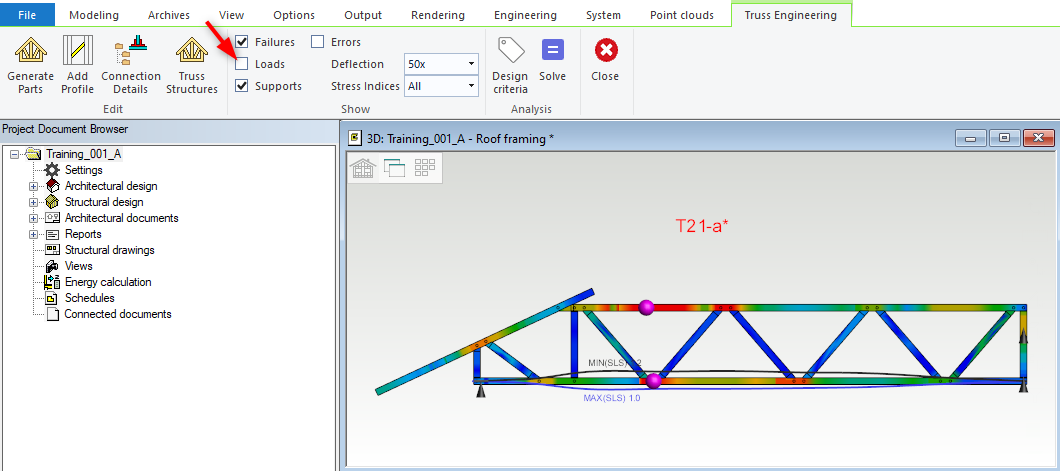
Stress index gradient colors clearly shows critical points in the truss structure.
-
We will add web pair without regenerating parts. ( Add Web Pair tool saves time )

-
loads can be turned off for batter visibility
-
Select the top chord and then the + symbol get activated.
-
Click on the the + symbol. It will add add diagonal pairs ( web pair ).
Diagonal pairs can also be removed, While this + ( Plus ) symbol is active right click and from the drop-down menu click on 'Remove Web Pair'.
-
Now click on 'Solve' to run truss structure capacity check.
-
The truss have failed structure capacity check.
-
Error message have been displayed to the left side in vertex window.
-
Only after closing the 'Calculation messages' box, further action can be taken such as add/removing web pairs, adding side reinforcement etc.
-
We will add side reinforcement to top chord.
-
Click on 'Connection details'
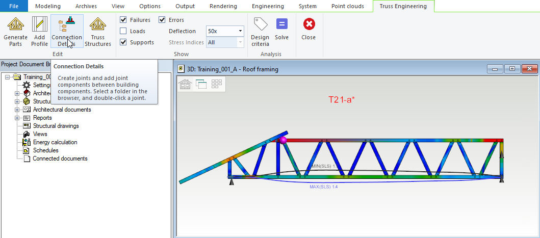
-
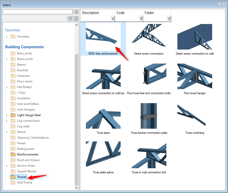
In the select box select 'Trusses' folder and click on 'Side reinforcement'
-
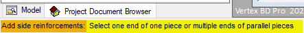
Pay attention to the instructions displayed at the bottom left of the vertex window
-
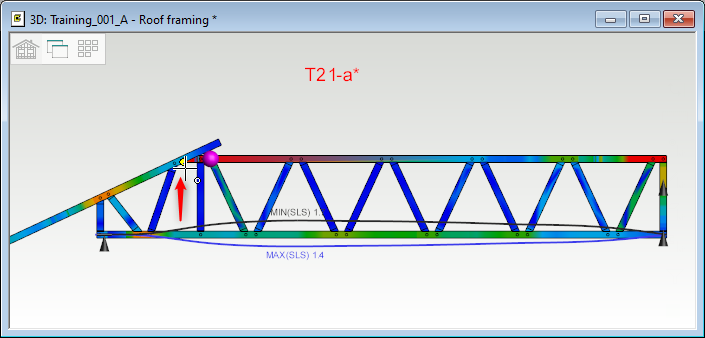
In this case we want to add side reinforcement to top chord, so select the top chord of truss. Right click and click on OK to confirm
-
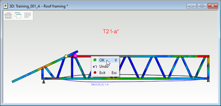
Select point 1 ( Click one end of the top chord )
-
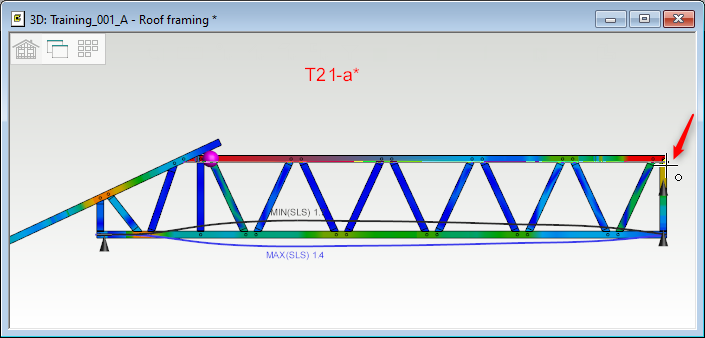
Select Point 2 ( Click other end of the top Chord )
-
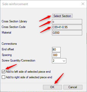
In this 'Side reinforcement' box you can choose the C-Section library and section code by clicking on 'Selection Section' button .
-
You can also choose whether to use side reinforcement Left or Right side of selected piece.
-
Click on OK
-
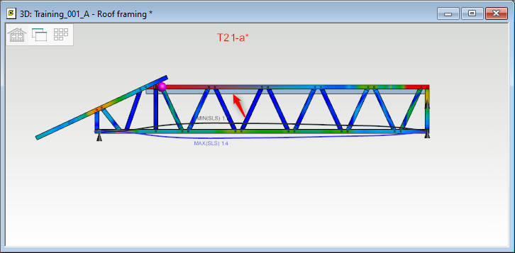
Now the side reinforcement have been added to the top chord of the truss.
-
Click on 'Solve' to run truss structure capacity check.
-
As you can see that the truss has passed the structure capacity check.
-
You can see the Stress index shown in gradient colors also makes it easier to see critical points in the truss structure.
-
Now you can fix errors in a similar process for the rest of the failed trusses
-
Once all the errors are resolved in one/single truss engineering one by one. As you exit one truss engineering window and come back to roof model pair you will notice the trusses that had already passed, the labels for those trusses will now turn Orange.
Once all the errors are resolved, again run 'Members and Trusses' for all trusses to confirm load transfer. Vertex will take its time to calculate the structural arrangements. ('Design criteria' box may popup, check the loads and click on OK) When done, the screen come to a halt, that is when you need to Select all the trusses (by holding down ‘ctrl’ ‘A‘) and press ‘V’ to confirm. Vertex will check, all truss structure parameters and design criteria. Trusses that pass structure parameters and design criteria, labels for those trusses will turn Green.
7. Run ‘Members and Trusses’ a final time for all trusses to confirm load transfers:
-
While you are in 'Roof' model pair, go to ‘Engineering’ tab, Click on 'Members and Trusses' to load transfer for all trusses to confirm. Vertex will take its time to calculate the structural arrangements.
-
'Design criteria' box may popup, check the loads and click on OK.
-
When done, the screen come to a halt, that is when you need to Select all the trusses (by holding down ‘ctrl’ ‘A‘) and press ‘V’ to confirm.
-
Vertex will take time to check, all truss structure parameters and design criteria. When done right click and click on OK to confirm
-
When all the trusses pass all structure parameters and design criteria, truss label will turn Green.