-
The default panel breaks are defined in the project parameters ( Min and Max Wall panel length ). Before we generate wall panel, first we will manually add 'Panel Break' ( panel macro ) to the ground floor plan.
Manual Panel Break
-
First we need to change to ground floor drawing model pair.
-
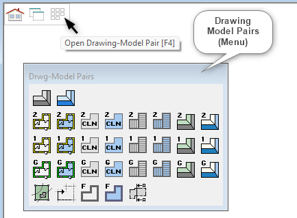
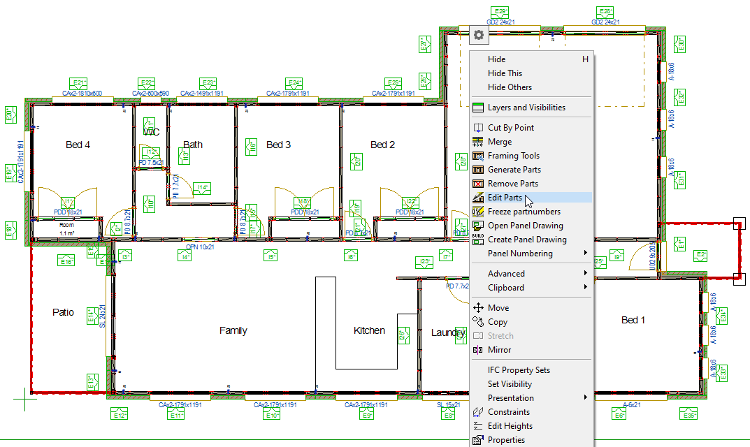
Click on these squares at the top left corner of the Vertex window ( as shown ) to activate the ‘Drawing Model Pairs’ menu.
-
If it hasn't appeared just press ‘F4’ to activate the ‘Drawing Model Pairs’ menu.
-
Select on the Ground Floor walls layout as shown
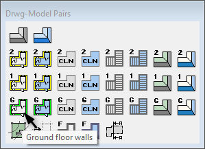
This 


Auxiliary functions may be related to the function you have selected. Auxiliary functions can be found in the context-sensitive menu. Open the menu by right-clicking at the exact point in the working window. You can select several auxiliary functions ( in 2D view ) from the menu. The menu closes when you move the cursor outside the menu. You can reopen the menu by right-clicking.
-
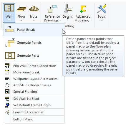
In 'Modelling' tab click on 'Wall' icon and from the drop-down menu click on 'Panel Break'.
-
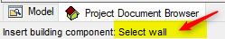
Pay attention to the instructions at the bottom left corner of the vertex window.
-
Vertex prompts you to select a wall. After selection of wall a cursor changes to represent the 'Panel Break' and locks into the selected wall.
Just in case you have selected a wrong wall OR want to select another wall in different direction after adding 'Panel break', you can still exit the wall by right clicking and from the contextual menu click on OK . Then you can select the right wall that you want to add the 'Panel Break' in. To exit the ' Panel Break' command press ESC key on the keyboard. You can also relocate the panel macro by dragging the grip point before generating the panel breaks. Note that after generating the panel breaks, the macro and the break point are no longer connected.
-
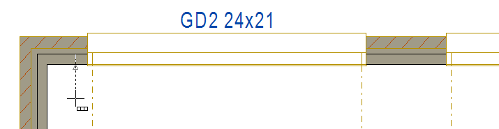
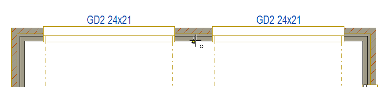
In this exercise we want to break Garage door wall in the middle. So move your cursor towards middle as you see this

-
Now 'Panel Break' have been added in the middle two garage door.
-
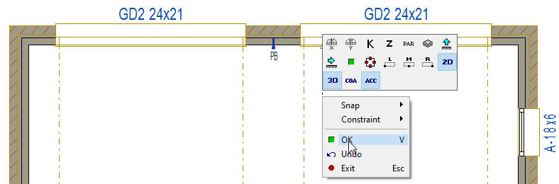
Right click and from the contextual menu click on OK to exit from the wall.
-
Remember that even though you have exit the wall but you are still in 'Panel Break' command.
-
You can keep adding 'Panel Break' to other walls if needed otherwise press 'ESC' to exit the 'Panel Break' command.
This contextual menu also lets you to manipulate 'Cut Out Width' of 'Panel Break' by selecting 'PAR'. While you in contextual menu, you can hover over each image ( hold the cursor for 1 to 2 second ), will display it's relative auxiliary function. You can select an auxiliary function even in the middle of selecting a wall point.
Generate Panels ( Automatic Wall Panel Break-up )
-
Once the manual panel breaks have been positioned, it is time to generate the automatic panel break.
-
Automatically placing panel break can be adjusted later.
-
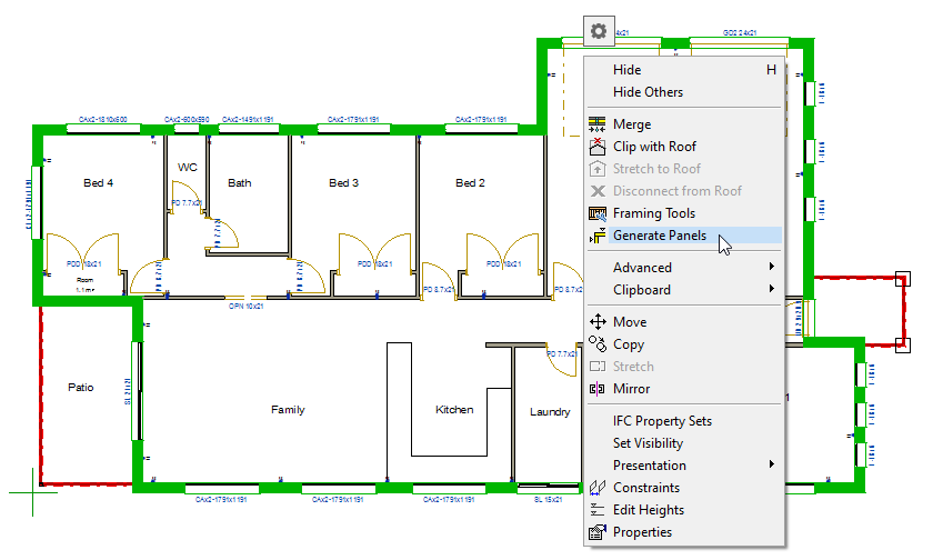
Select an External Wall and then press CTRL A to select all the External Walls.
-
Right click and from the contextual menu click on ‘Generate Panel ’
-
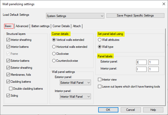
In this 'Walls panelizing settings' dialog box under 'Basic' tab you can can select the followings
-
Structural layers,
-
Corner details (overlap type)
-
Set panel labels,
-
Viewing direction of the panel.
-
-
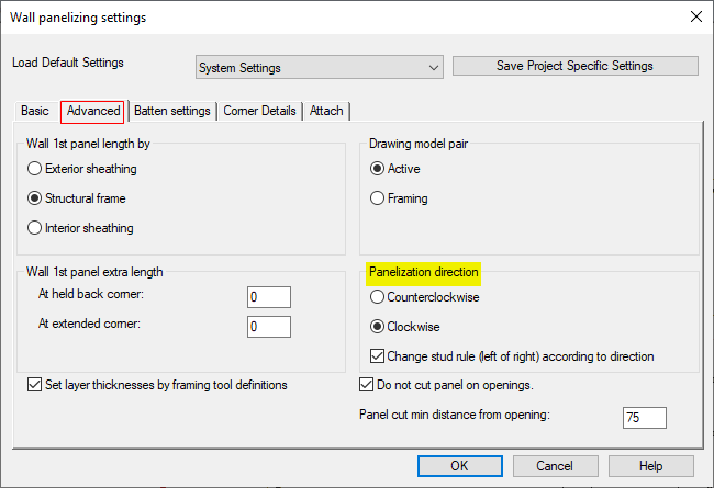
Other important settings is under 'Advanced' tab
-
Penalization direction
-
Panel cut min distance can be increased from min 75mm ( Default ) to 90mm or 100mm as per the requirement. In other words In this dialog box you can adjust how the panels are created.
-
-
Once done click on OK.
-
Repeat this process for the internal walls.
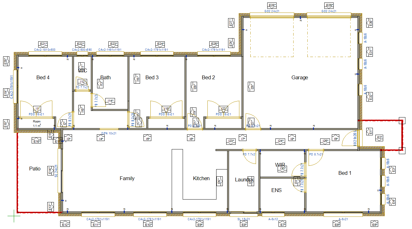
-
You should now have panel breaks and panel numbers added to the plan as below.
Adding Beam pockets
-
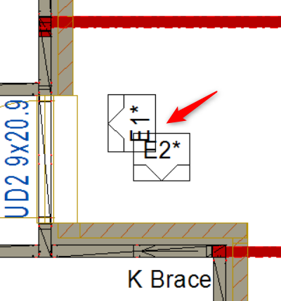
Steel beam end (near rear patio and the entry) sit into walls. Therefore we need to create beam pockets to accommodate these Steel beam into the wall frame.
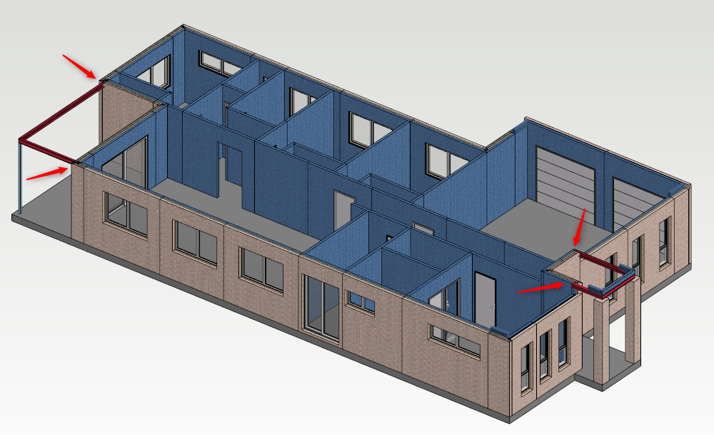
If beams are not visible in layout, switch back to 3D view. Select the beam/s. right click and from the contextual menu click on 'Set Visibility'. That will bring up ‘Select drawing-model Pair’ window on the left hand side of the screen. Tick the check box for the intended modal pair layout and don’t forget to click on OK.
-
Press 'F2' to switch to 2D view of Ground floor Walls Layout and zoom into the top left hand corner.
-
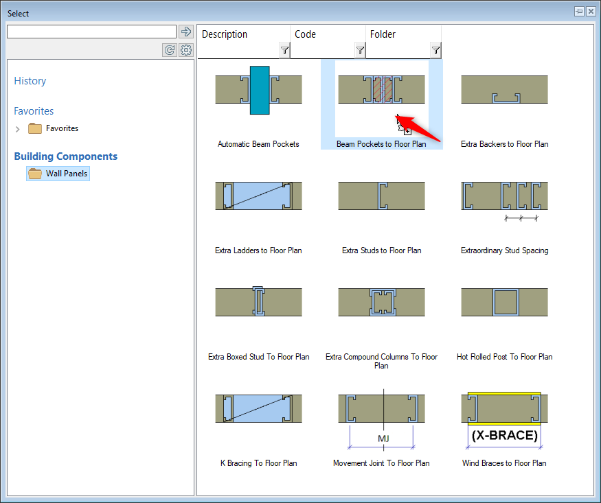
In ‘Modelling tab’ click on the Wall icon → ‘BR Wall panel layout accessories’.
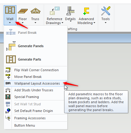
-
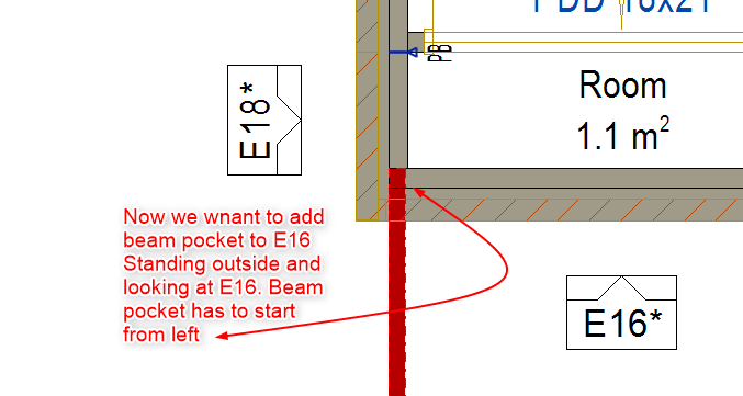
Select ‘Beam Pockets to Floor Plan’ option.
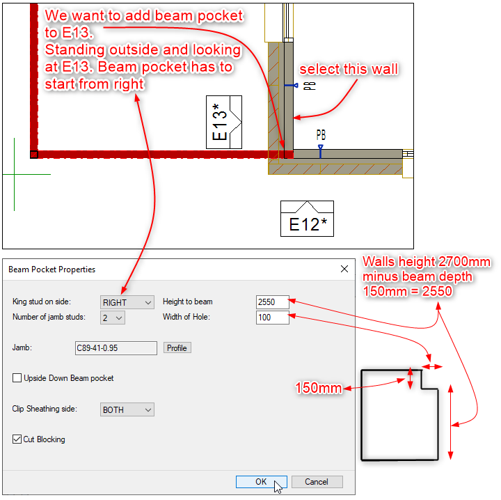
In the corner situation you only want a King Stud on one side. The orientation of the wall panel is taken as reference and looking from the outside, therefore we will pick the right side for the stud. Height of the beam means, at what height beam must sit. The width of the hole is to suit the size of the beam.
-
Click on the wall ( that you want to create beam pocket in )
-
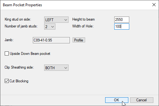
‘Beam Pocket Properties’ dialogue box will appear as shown
-
Fill out the dialog box to suit and click on OK.
-
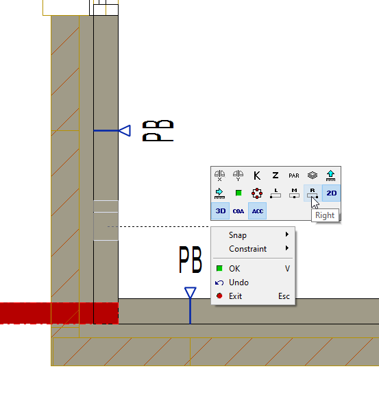
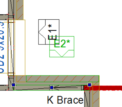
select the wall ( now as you see that the holding position need to be changed to right ) so right click and from the contextual menu select 'R' ( right )
-
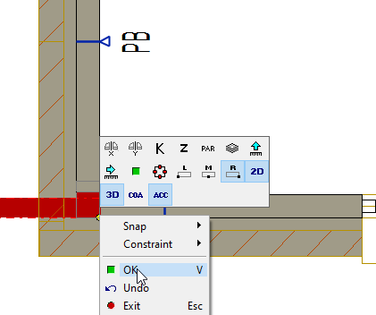
Position 'Beam Pocket' at the corner ( as shown ) right click and click on OK to exit the wall. Remember that the cursor is still in beam Pocket command. ( Until you press ESC to exit the command )
-
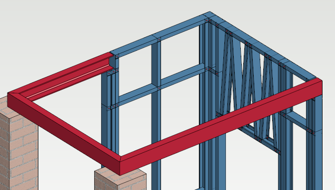
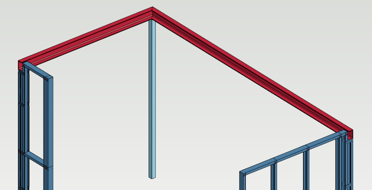
After generating parts, you will notice that the frames are created with the beam pockets. ( you may have to move, flip the stud and add connections to suit )
Generate Parts ( for Wall Panels )
-
Make sure that you switch back to Ground floor wall layout. ( 2D view )
-
Select on one of the external and one internal wall panel numbers ( in 2D view )round floor layout ), hold down Ctrl key. Press CTRL A. This will select all of the wall panels.
-
Right click and form the contextual menu pick ‘Generate Parts’.
This will create all the steel frames and parts. ( It might take little time so be patient ).
-
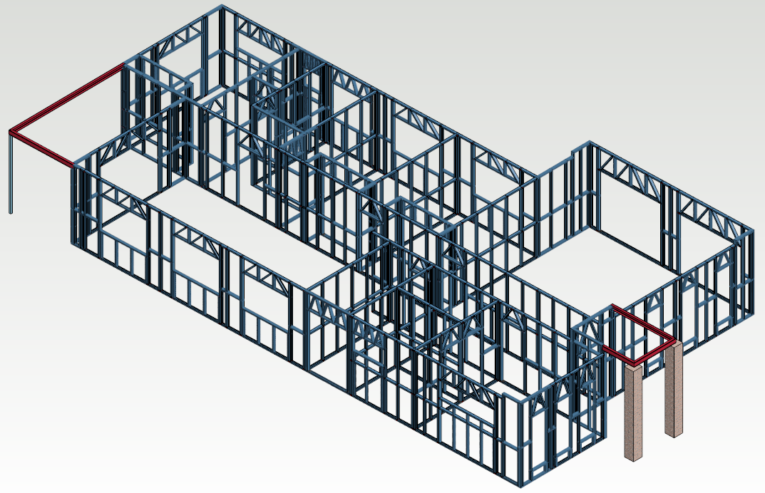
After wall frame parts have been created, switch to the Ground floor Wall Framing 3D view to inspect your framing.
-
You can select panel or even individual pieces to modify and manipulate them either in 2D or 3D. See next section.
Additional Topics
How to move Wall Panel Number on layout ( Plan View )
You can easily move wall Panel Number. There may be a number of reasons why you need to move wall panel Number.
-
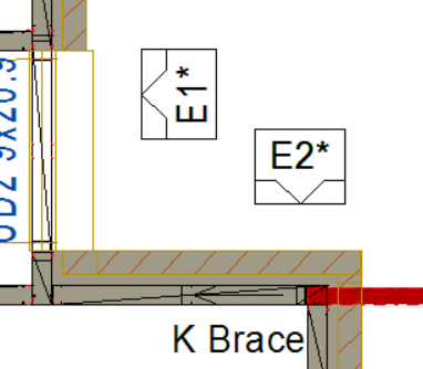
For example, you have a number that is clashing / protruding in another number. You may need to move the wall panel number for better visibility.
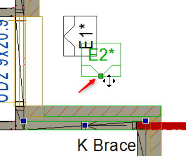
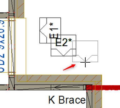
1. Click to select the wall panel number that you want to move. The selected panel number will turn green ( as shown below ).
2. Move / hover the mouse to the lower middle of the numbered grid. A small green square will appear. Click the small green square to drag the wall panel number to the desired place .