-
You can add, move studs/nogs and add bracing etc to frames. Framing connections can be altered as per the requirement. Generally these four ( Swaged joint, Notched joint, Swaged Corner joint and Continuous joint ) types of joints are mainly used.
-
You can even have multiple browsers opened and pinned on the screen ( such as 'Connection details', 'Framing accessories' and so on ) to speeds up design and editing. Refer to Library Browser 2020 for more details
Add K-Brace to Steel Frame
-
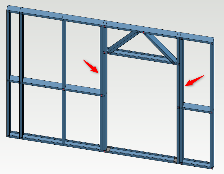
In this training exercise we will add some K-Bracing and Strap bracing to several panels.
To select one whole frame in 3D framing view, hold down ALT key first and then you select the frame.
OR
If you want to select more than one frame in 3D framing view, you need to hold down CTRL along with ALT key first then you select the frames one by one.
-
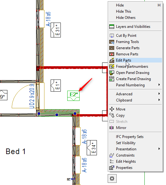
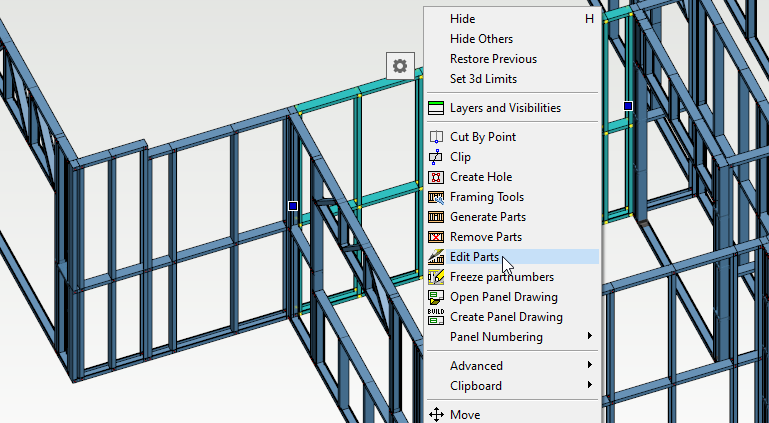
You can select wall panel in either of 2D or 3D but in this scenario we will select wall panel mark/number in the 2D view. Right click and from the contextual menu select ‘Edit Parts’.
-
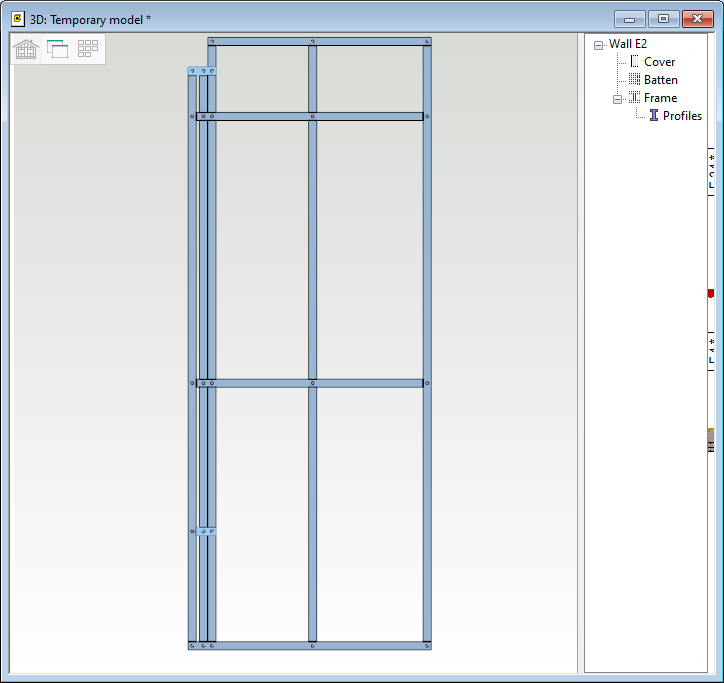
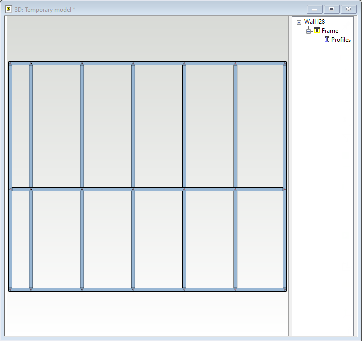
This will bring up a '3D Temporary model' view of the preselected Walls panel.
-
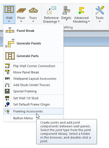
While you are in this '3D Temporary model' view, go to 'Modelling' tab → 'Walls' icon and from the drop down menu select ‘Framing Accessories’.
-
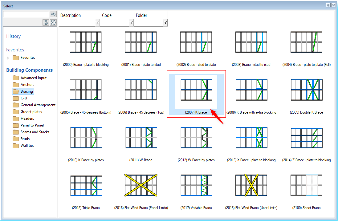
In 'Bracing' folder double click on the 'K-Brace'.
-
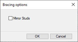
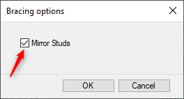
Bracing option dialog box pops up. Now whether to tick 'Mirror Studs' or not, it all depends on the direction of the studs and the direction selected by the user while inserting K-Brace in the frame.
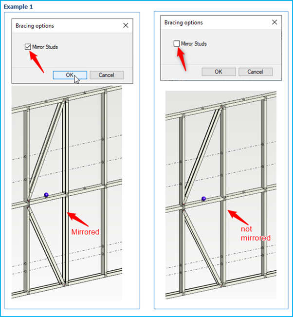
Whenever you are in edit parts mode '3D Temporary model' view, you will notice that the orientation / start of the frame is always from left to right and generally in most cases studs will be facing towards the right. Therefore you don't have to tick the 'Mirror Studs' check box if you are adding K-brace, with ‘Pick place Select point 1' near the lower right corner of the bay and the ‘Pick place Select point 2’ near the top left corner of the bay ( space between the two studs ). Refer to EXAMPLE 1 picture 2
-
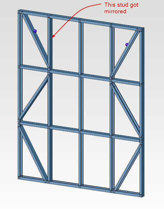
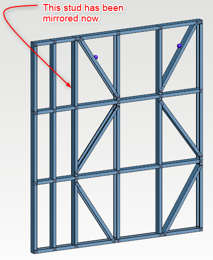
You can tick the “Mirror Studs” check box if you want next stud to the K-Brace to be mirrored as shown below Example 1, Picture 1
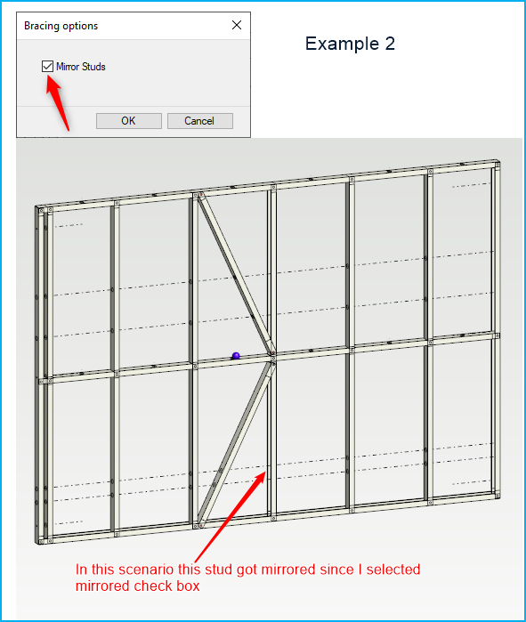
Whenever you are in edit parts mode '3D Temporary model' view, you will notice that the orientation / start of the frame is always from left to right and generally in most cases studs will be facing towards the right. Therefore you can tick the 'Mirror Studs' check box if you are adding K-brace, with ‘Pick place Select point 1' near the lower left corner of the bay and the ‘Pick place Select point 2’,near the top right corner of the bay ( space between the two studs ). Refer to EXAMPLE 2
-
You can also tick the “Mirror Studs” check box if you want to mirror the stud that the K-brace is screwed on to (near nog line). As shown in Example 2.
-
It all depends on the direction of the studs and the direction selected by the user while inserting K-Brace in the frame.
-
In this case we will tick the 'Mirror Studs' check box and click on OK.
-
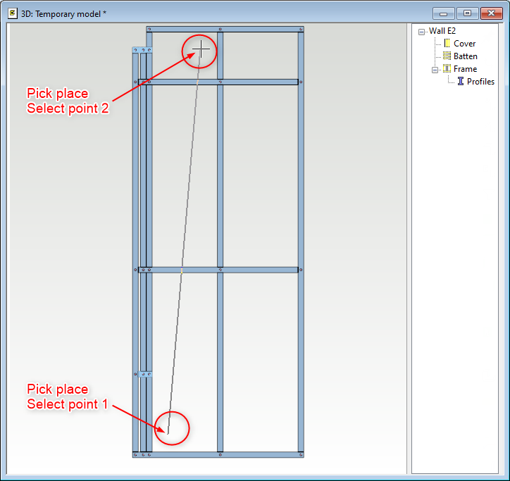
The Vertex prompts you to ‘Select Wall Panel’, in the '3D Temporary model' view.
-
The next instruction is to ‘Pick place Select point 1’, you need to pick near the lower left corner of the bracing area.
-
Now pick ‘Pick place Select point 2’,near the top right corner of the bracing area.
-
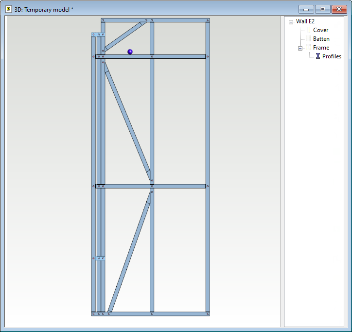
The K-Bracing will be automatically connected into the wall frame.
-
The orientation of the bracing can be reversed by clicking the both selection points ( point 1 and point 2 ) near the opposite corners when inputting the brace.
-
Purple mark ( ball ) indicates the macro have been added to the wall frame. Now even if you regenerate parts again K-brace will appear in the frame.
-
If you delete this purple mark ( ball ) macro and regenerate parts again, K-brace will disappear from the frame
-
Now experiment with some of the different types of bracing provided.
Add Flat Wind brace ( Strap-Brace ) to Steel Frame
-
You can select the wall panel in either in 2D or 3D but in this scenario we will select wall panel in the 3D view. Right click and from the contextual menu select ‘Edit Parts’.
-
This will bring up a '3D Temporary model' view of the preselected Walls panel.
-
While you are in this '3D Temporary model' view, go to 'Modelling' tab → 'Walls' icon and from the drop down menu select ‘Framing Accessories’.
-
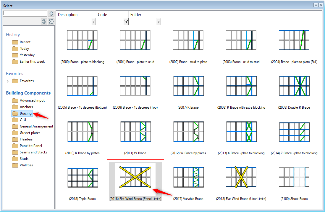
In 'Bracing' folder double click on the 'Flat Wind Brace'.
-
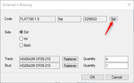
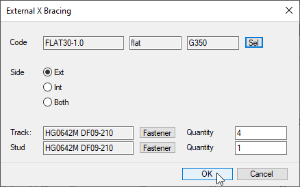
Now in this dialog box you can select the required code. You can choose whether you want the Strap brace Externally, internally or both sides of the wall panel. You can also choose fastener quantity to track and stud
-
Click on 'Select'
-
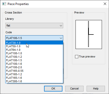
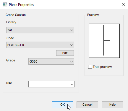
In this dialog box change the Code to 'FLAT30-1.0' and click on OK
-
Now you can see that the code has been changed to 'FLAT30-1.0'.
-
We will accept rest of the default settings and click on OK
-
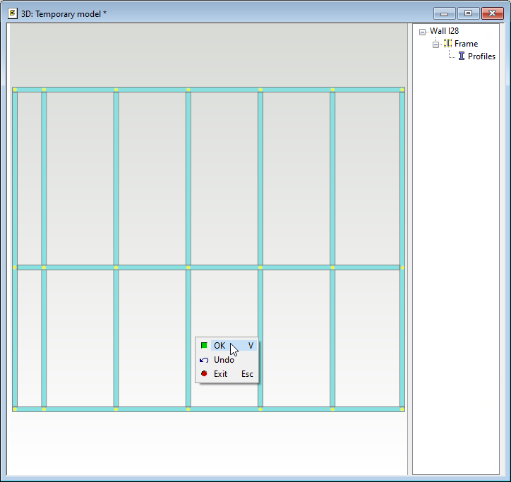
Vertex will prompt you to 'Select Wall panels'. So select the wall panel. Right click and click on OK to confirm or Press 'V' to confirm
-
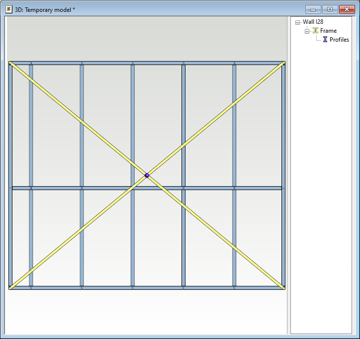
The Flat Wind Bracing will be automatically connected to wall frame.
-
Purple mark ( ball ) indicates the macro have been added to the wall frame. Now even if you regenerate parts again Flat Wind Bracing will appear in the frame.
-
If you delete this purple mark ( ball ) macro and regenerate parts again, Flat Wind Bracing will disappear from the frame
-
Now experiment with some of the different types of bracing provided.
Additional exercises
Edit Wall frames through Framing tool settings
SCENARIO 1 _ Set stud under the truss
-
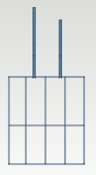
We have a load bearing wall that have trusses over it and we want wall studs to align with trusses and rest of the studs have to be equally spaced.
-
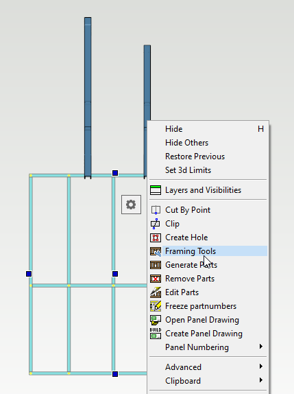
Select the wall either in 2D or 3D view. Right click and from the contextual menu select 'Framing Tools'
-
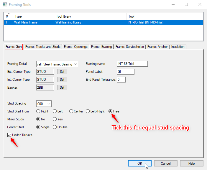
In 'Framing Tools' dialog under first tab 'Frame Gen' ( generate ) tick as shown and click on OK and Generate parts for the frame.
-
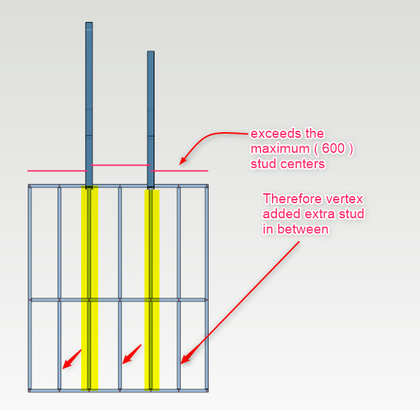
Since stud spacing is 600 centers max. and while having studs under trusses, if the stud space exceeds the maximum stud centers vertex will add extra stud ( equally spaced ) between the exceeded studs space .
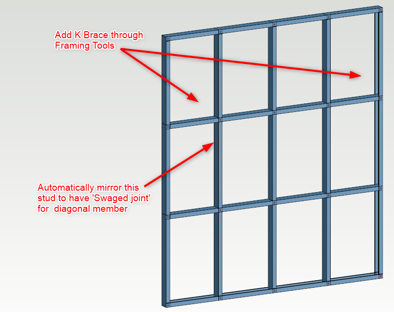
SCENARIO 2 _ Automatic K -brace macro to panel
-
We have a wall and we want to add K Brace at right and left side through the framing tools automatically . Also we want diagonal member 'Swaged joint' to stud NOT 'Notched joint'
-
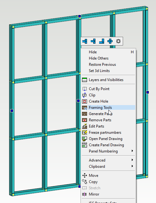
Select the wall either in 2D or 3D view. Right click and from the contextual menu select 'Framing Tools'
-
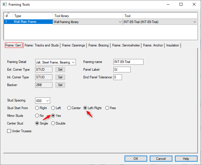
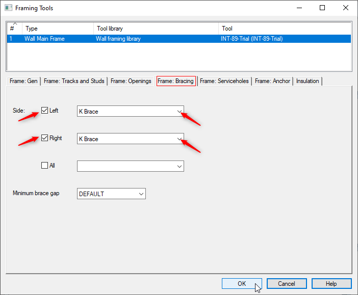
In 'Framing Tools' dialog follow as shown below click on OK
-
Generate parts for the frame.
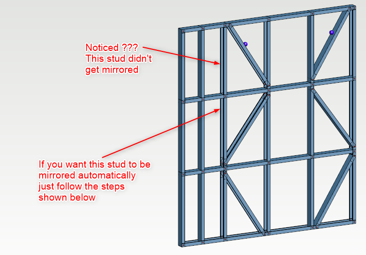
SCENARIO 3 _ Automatic K -brace macro to panel with mirrored stud
-
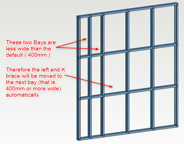
Suppose we have the same wall but the one end is less than the default ( stud spacing for K brace 400mm ) in that case left end K brace will be moved to the next bay ( that is 400mm or more wide ) considering the scenario 2 framing tools settings ( K brace to left and right end of wall frame )
-
Generate parts for the frame.
-
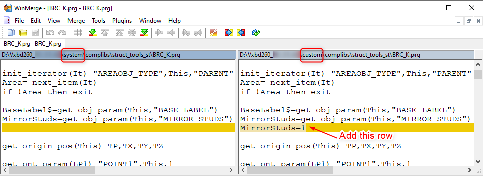
Go to your system \ complibs \ struct_tools_st and find this 'BRC_K.prg' file
-
Copy this 'BRC_K.prg' file to your custom \ complibs \ struct_tools_st folder.( if this struct_tools_st folder doesn't exist in your custom side, just create a new folder and name that to struct_tools_st ).
-
Open this 'BRC_K.prg' file in Notepad ++
-
Add this MirrorStuds=1 in new row as shown
-
Click 'Save' the file
-
Generate parts for the frame.
Add components and connections
-
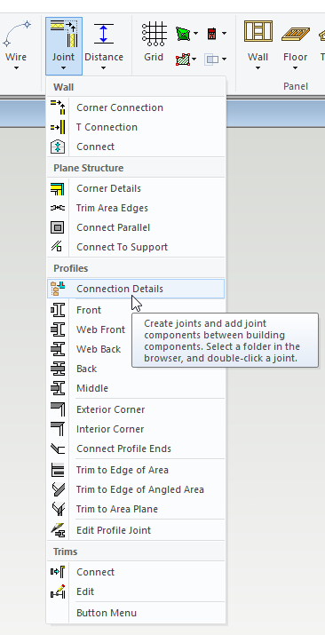
You can add different components, change or add missing connections from 'Modelling' tab →joint → Connection Details
-
Connections can be added to frames in 3D view.
OR
-
Select panel/s to be edited in 3D view or 2D view. Right click and from the contextual menu
select 'Edit Parts'.
-
That will open '3D Temporary model' window with elevation view of the preselected panel/s.
-
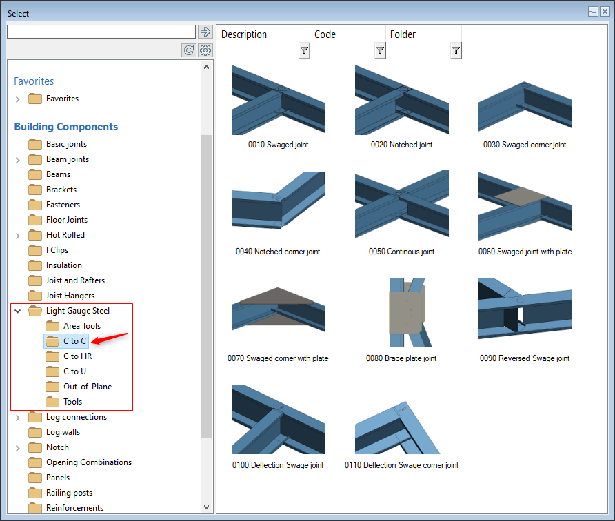
Select the joint type and follow the prompt. ( e.g. select Track and then select pieces ).
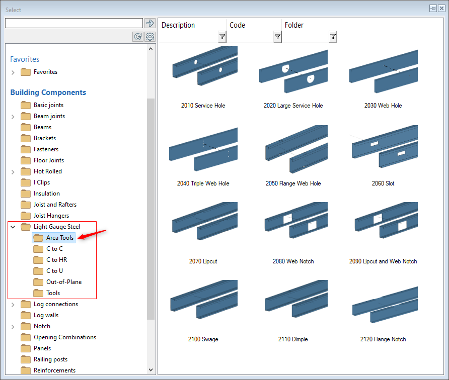
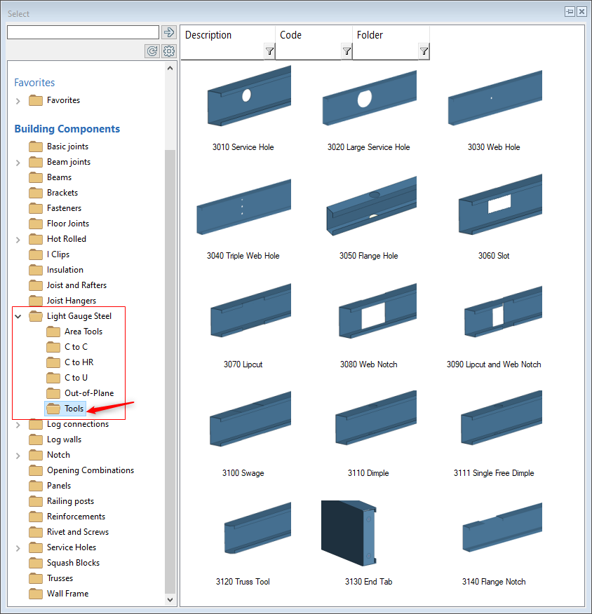
If you want to add additional service holes to the steel frame, you have to add from these 'Area Tools and 'Tools' folder.
Please don't add service holes to steel frame from the 'Service Holes' folder. if you do so you may see the service holes in the model but when you create 'NC Output' files, service holes won't be there in the steel frame ( Since 'Service Holes' folder is for adding the service holes to timber wall frames only ).
-
You can use 'Area tools' to add additional components such as service holes, web holes, notches etc to multiple studs at a time.
-
Select panel/s to be edited in 3D view or 2D view. Right click and from the contextual menu select 'Edit Parts'.
-
That will open '3D Temporary model' window with elevation view of the preselected panel/s
-
Select the component and follow the prompt.
-
Pay attention to the instructions at the bottom left corner of the vertex window
-
You can use 'Tools' to add additional components such as service hole notch, web hole, notch, etc to single stud at a time.
-
Select panel/s to be edited in 3D view or 2D view. Right click and from the contextual menu select 'Edit Parts'.
-
That will open '3D Temporary model' window with elevation view of the preselected panel/s
-
Select the component and follow the prompt
-
Pay attention to the instructions at the bottom left corner of the vertex window
Box Studs
-
To add a stud or any other customised Framing accessory you must first activate a working plane and then indicate the stud/location of boxed element.
-
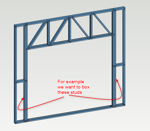
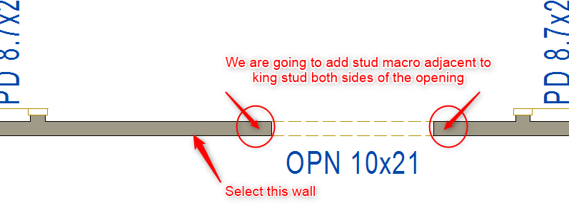
In this scenario we will box king studs both sides of the opening.
-
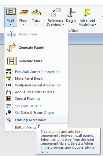
Under ‘Modelling' tab click on ‘Wall’ icon and from the drop-down menu click on ‘Framing Accessory’
-
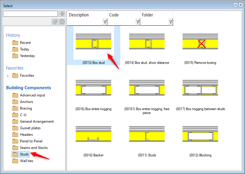
Select the correct tool ( as shown ) by Double clicking on icon
-
Pay attention to the instructions at the bottom left corner of the vertex window
-
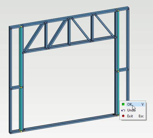
Vertex prompts to 'Pick stud' ( hold down CTRL key to select more than one stud ) right click and click on OK to confirm OR press 'V' to confirm.
-
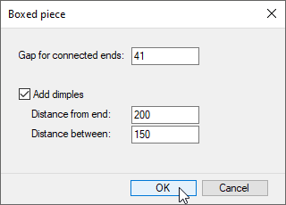
Gap for connected ends can be changed as per the requirement as well as Screw distance from end and distance between screws can also be changed as per the requirement.
-
In this scenario we will accept the default by clicking on OK
-
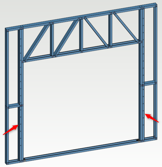
You can see second king stud on both sides of opening have been boxed. You can also see the screw distance from end and the distance between the screws as well.
-
Now even if you regenerate parts for this frame boxed stud will be there.
-
To delete the boxed stud, you will need to go to ‘Modelling' tab → ‘Wall’ icon and from the drop-down menu click on ‘Framing Accessory’
To delete the box stud double click on this 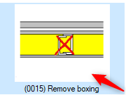
Vertex will prompt to 'Pick Stud'. So select the boxed stud. Right click and click on OK to confirm or Press 'V' to confirm.
Now the boxed stud will be deleted
Add Stud/s to floor plan
-
If you need to add studs macro either back to back or any other combinations, it is easy to do it in 2D layout using the following procedure.
-
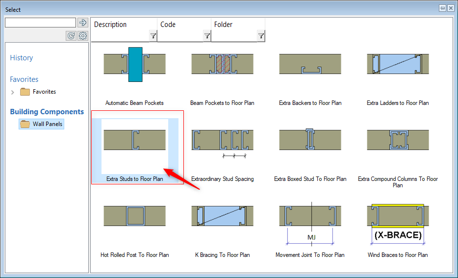
In ‘Modelling Tab’ click on ‘Wall’ icon and select ‘‘BR Wall-panel Layout Accessory’
-
Select the correct tool ( as shown ) by Double clicking on icon
-
Pay attention to the instructions at the bottom left corner of the vertex window.
-
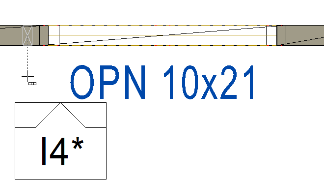
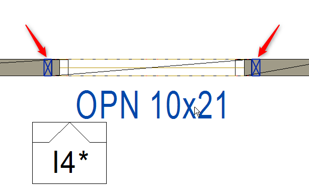
Vertex prompts to 'Select Wall' so select the wall for example 'I4' ( as shown )
-
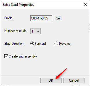
Extra stud property dialogue box appears. Select the right gauge ( number of the studs can be altered depending on the requirement ) In this case we will accept default values and click on OK
'Q' command can be used to set the local reference point. Drag the cursor in the intended direction to and type the distance as per the requirement to place the stud macro in the frame.
-
Vertex prompts to 'select wall' again. So Select the wall ( in 2D view ) where studs are to be applied. After selection a cursor changes to represent stud/s and locks into the selected wall.
-
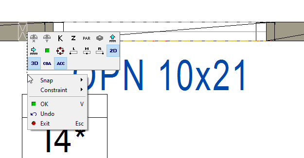
Right click and a new set of contextual menu appears. Choose options ( such as Left, Middle, Right ) for accurate placement of the stud.
-
A good tool to locate a stud is “distance from given point”.
-
Place the stud macro as shown
-
Zoom in to see and click adjacent to the king stud. Right click and click on OK to confirm or press 'V' to confirm.
-
While keeping the command active Flip studs direction form the contextual menu by clicking Mirror X .
-
Now zoom in to the other side of the opening and click right to the king stud. Right click and click on OK to confirm or press 'V' to confirm.
-
Press ESC to exit the command.
-
press F2 to switch to 3D framing view.
-
Stud macro have been added adjacent to the king stud each sides of the opening. but you need to 'Generate Parts' to see the stud macro.
-
Even if you regenerate parts for this frame stud macro will be there in the frame until you delete it manually.