General
Working with Vertex G4 connected to Flow differs from modeling without Flow primarily in the following ways:
-
Models and drawings are stored in Flow, not in Vertex G4's archive.
-
Components of the component library are primarily listed as items in Flow's archive.
-
Profiles used in structural design are listed as items in Flow.
-
Raw materials are listed as items in Flow.
The items for components, profiles, and raw materials needed by the customer are generally exported to Flow during the implementation of the Flow system, and the customer can later supplement them themselves.
Vertex G4 still uses a model and drawing archive, where models and drawings are read from Flow for editing upon opening, but the primary storage location is Flow.
-
The project archive of Vertex G4 is not used with Flow.
-
The models and drawings contained in Vertex G4 projects are exported to Flow and linked to corresponding project objects during the implementation of the Flow system.
See also:
Working with Vertex G4 in conjunction with Flow: Vertex G4
Modeling and Parts Lists
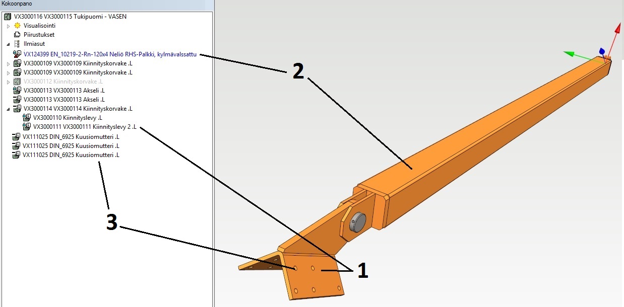
The items to be modeled can be divided into the following categories:
-
Drawing number parts and assemblies: These have their own model and one or more drawings.
For example, in the image: VX3000111 Mounting Plate (1) -
Materials: These are purchased based on the item information, and the geometry representing the item is visible in the assembly.
For example, in the image: VX124399 Square RHS Beam (2) -
Purchased components, such as fasteners, bearings, electric motors, valves, etc.
For example, in the image: VX111025 Hex Nut (3)
In addition, the product includes items that are not modeled at all, such as lubricants, sealing adhesives, etc. They do not appear in the CAD model but are still included in the parts lists because they belong to the product structure.
In the assembly, drawing number parts are displayed in the drawing tree with the suffix ".L".
Part Model
A part model describes a single part that consists of only one raw material.
-
The parts list of the part model shows the details of the raw material item associated with the part.
Assembly Model
An assembly model describes a product or semi-finished product that consists of multiple parts.
-
The parts list of the assembly shows the item information for the parts contained in the assembly.
-
The parts list may also include items that are linked to the structure in Flow but do not have geometry in the model.
Is the model or drawing in Flow or not?
The color of the symbol for the part or assembly model indicates whether the model is stored in Flow.
Yellow color
The model is stored in Vertex G4.
The main symbol in the drawing tree is yellow even for models stored in Flow if the model has been read for viewing.
Green color
The model or drawing is stored in Flow.

Drawing and Parts List
This section addresses drawings that are not produced from 3D models but are drawn "manually."
-
Such a drawing cannot directly represent the item structure in the same way as a 3D assembly, as the drawing is always a more or less symbolic representation of reality.
-
Part numbers are linked to the drawn geometry, referred to as attributes in the item data from Flow's item catalog.
-
Thus, the product structure is created based on part numbers.
-
A part number that does not have associated item data will not be included in the structure.
By double-clicking on a part number, you can access the associated property display, from which you can retrieve the item from Flow.
Add Part Information to the Drawing
-
Add part numbers to the drawing using the option Drawing | Mechanical > Part Number.
-
Start adding part information using the option Drawing | Mechanical > Part Information.
-
Click on the part number to which you want to add the item.
-
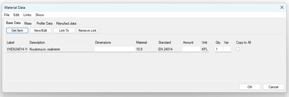
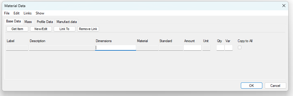
Vertex G4 will open the Material Information dialog box.
-
-
Select the option Get Item.
-
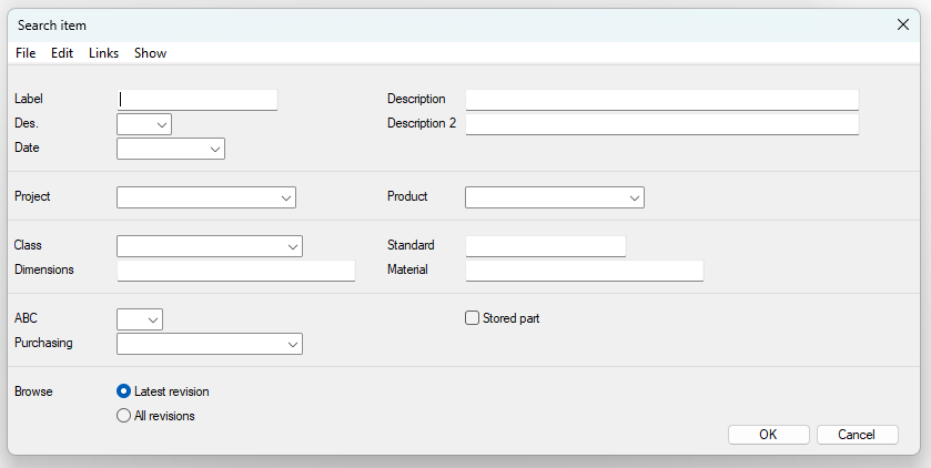
Vertex G4 opens the Search for Items dialog box.
-
Select or enter search criteria.
-
A good search criterion is a classification, which opens the Select Classification dialog box.
Select the classification by clicking on it.
-
-
Confirm the search criteria by selecting OK.
-
Vertex G4 lists the items that match the search criteria.
-
-
Select the item.
-
The item information is transferred to the part number.
-
(8) Edit the material information as needed.
-
The Dimensions field may contain, for example, the length of a profile or the main dimensions of a sheet blank if the unit of measurement is, for example, mm, m, or m².
-
The Quantity field may contain weight or volume if the unit of the item is, for example, kg or dm².
-
The Count field may contain, for example, the number of screws if the unit of measurement is pieces.
Fields displayed in gray are properties related to the item and cannot be changed here.
-
Item property information can be modified in Flow, as long as the item is first reserved.
(9) Confirm the part or raw material information you have selected and entered by selecting OK.
(10) Repeat steps 3...9 for all part numbers in the drawing.