
General
A sheet metal part in Vertex G4 is a component model that is defined as a sheet metal part in the part properties.
-
Modeling procedures can be performed on sheet metal parts that cannot be done on regular parts.
-
Handling of sheet metal parts requires the Sheet Metal Design option for Vertex G4.
-
You can see the options by selecting File > This program version.
-
This guide provides a general example of how to add a sheet metal item to an assembly, model its geometry, save it as its own item (and component model), and create a drawing for this model that includes a parts list considering cut-out dimensions.
For additional guidance on modeling sheet metal parts in Vertex G4, press the F1 key to open the help documentation.
-
See instructions related to modeling sheet metal: Geometry 3D > Component Modeling > Sheet Metal (additional option).
Working with Vertex G4 in conjunction with Flow: Vertex G4
Basics
In the design of sheet metal parts, it is essential to consider the manufacturability of the component. Once it is decided that a particular component will be made by bending sheet metal, it should be modeled in a way that allows for automatic calculation of the blank size with the correct stretches, as well as the amount of material needed for the part's fabrication.
The following example illustrates one way to model parts directly within an assembly and obtain the correct cut-out drawing (i.e., blank drawing) along with the material requirements.
Create a New Part in the Assembly
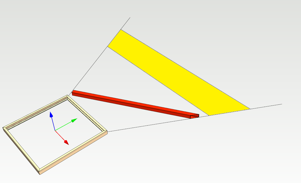
A composition (i.e., assembly item) is open in Vertex G4.
-
In this example, we want to add a treatment level to the area marked in yellow in the image.
Add Item to Assembly
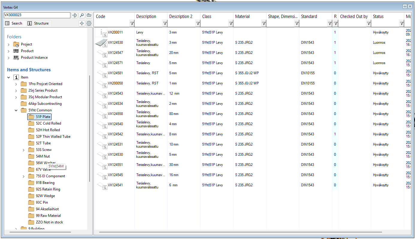
Open the browser and search for the sheet metal item.
-
Drag and drop the item into the assembly.
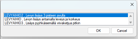
Sheet material can be added to the assembly in three ways.
-
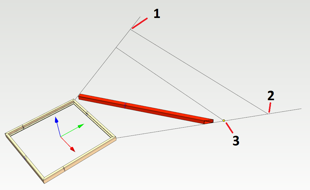
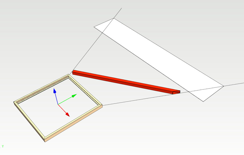
This example demonstrates the addition of the sheet using three corner points. We will select the addition method using three points:
-
Our sheet metal part in the assembly now looks like this.
-
The sheet metal part is currently a local part, meaning it does not have its own part number or model file.
Change the part to a sheet metal type so you can perform operations allowed for sheet metal parts:
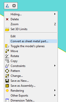
The sheet is to be trimmed relative to the edge tubes, and then two bends will be made to the sides of the tubes.
-
The Edit with Parts function will be used for the trimming: Remove.
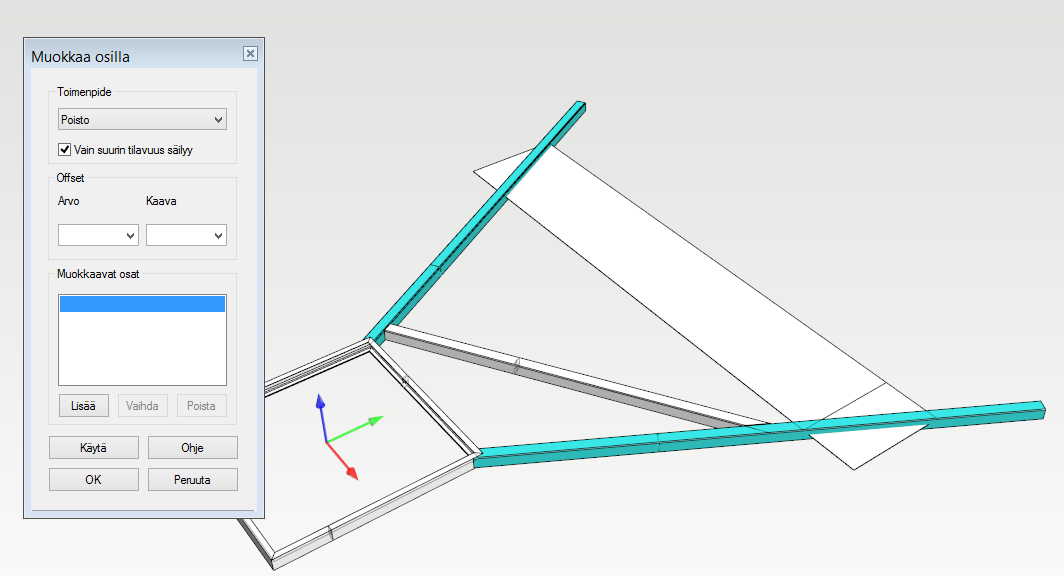
After that, the bends will be made using the standard sheet metal part bending drawing function:
-
Finally, we will return to the assembly state.
-
Since the part is still in the assembly as local geometry, no restoration actions are needed; we will just move up from the part level to the assembly level.
Save the part
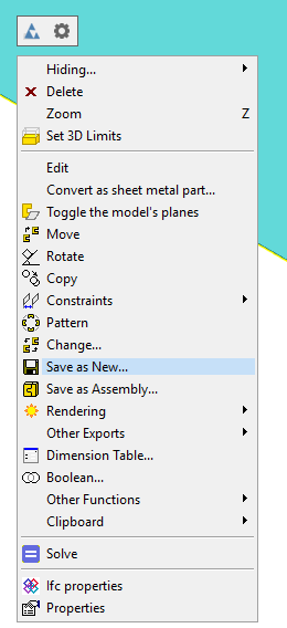
If and when you want to create a new item from the part that has its own working drawing, select this part in the assembly and create a new item by choosing Save as new.
-
This way, the raw material information of the local part geometry will be transferred to the structure of the newly saved item, creating a new intermediate level in the structure.
The part is highlighted in blue in the assembly tree because it has features that are determined by other parts of the assembly.
-
Thus, by changing the main dimensions of the assembly, the related parts also change.
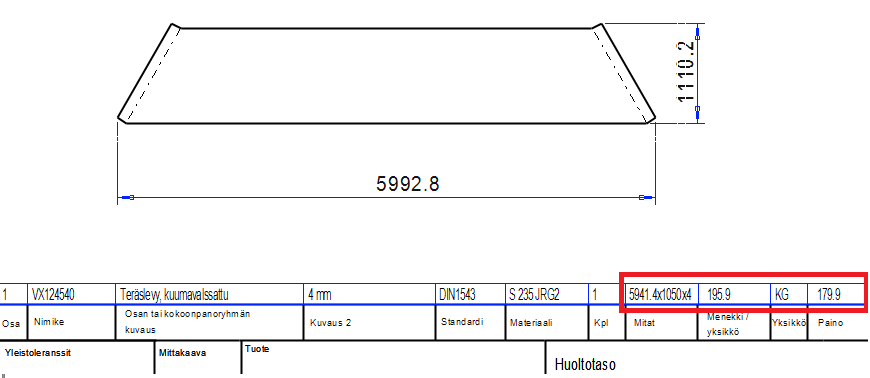
Create a drawing and parts list for the part.
Since this is a blanked sheet metal part, a flat layout projection will be created from it.
-
This will allow the program to calculate the material consumption and the weight of the part.
Technical Requirements
Sheet-type items must have a connection to the geometries that form the local part in the assembly.
-
These are usually pre-saved in Flow's models under the names LEVYAIHIO, LEVYAIHIO2, and LEVYAIHIO3.
-
The files can be requested from Vertex Systems' support service if needed.
Sheet Models
The property data must include the following definitions:
-
To calculate the material consumption, the field for the Consumption Formula is needed, for example, for kg- and m²-based items: kg = 0.001 * #L# * 0.001 * #K# * 0.001 * #t# * (DENSITY) | m² = 0.000001 * #L# * #K#
-
The value for Density is retrieved from the "Density" field of the associated item.
-
In the Dimensions field, the content must be #L# x #K# x #t#: this updates the blank dimensions in the parts list.
Additionally, the property "Do Not Update" must be set to on.
Item Information
The following definitions are required:
-
In the CAD Parameters field, it must be specified as L=?|K=?|t=5, where t represents the sheet thickness and is therefore an item-specific value; in this example, it is a 5 mm sheet.
Using this method with three sheet models, all sheet-like items can be represented regardless of their raw material, density, and unit.