General
The component or profile libraries of Vertex G4 connected to Flow should not be used. Instead, the required profiles and components for the customer should be saved in Flow as items.
-
These actions are typically performed during the implementation phase of Flow, in collaboration with an expert from Vertex Systems Oy.
-
For export to Flow, it's advisable to add the items and model identifiers to a standardized Excel spreadsheet, alongside the models related to the items. Vertex Systems Oy’s experts will provide additional information on this.
-
See: Creation of Item Catalogs and Libraries and Data Import and Export.
Working with Vertex G4 in conjunction with Flow: Vertex G4
Background
The models representing Vertex components and profiles are modeled as size-variant.
-
In other words, a single model of a U-profile can represent all sizes of that U-profile, and a single model of a hexagonal screw can represent all differently sized hexagonal screws with the same geometry.
-
Component models are generally three-dimensional sub-models created by sketching.
-
Profile models consist of sub-models containing only one cross-section.
In Flow, all items using the same geometry (e.g., U-beams or hexagonal screws) are linked to the same model, but the item has size-defining information in the Parameters field.
When adding items to an assembly, components and profiles are searched for just like any other items, meaning that the user does not need to know the specific geometry used for the item or from which folder the models can be found.
Technical Requirements
-
Each item must be linked to a model that has the geometry of that item.
Model Information
-
The model's properties must have the setting "Do Not Update."
Item Information
-
Each item must have defined dimensions for how that item is represented.
-
This information is in the Parameters field. For example, the dimensions for a 13 mm DIN 125 washer are d1=13| d2=24| s=2.5.
-
-
These dimensions correspond to the names of the parameters in the sketches and features of the model related to the item.
-
Refer to the Vertex G4 documentation under Geometry 3D > Sub-modeling > Tools > Dimension Tables for more details.
-
Save a Single Model as a Flow Component
Read Geometry into G4
Ready-to-use components and profile cross-sections are included with the G4 delivery package:
-
Components: ...\vxg4_srv\system\components
-
Profiles: ...\vxg4_srv\system\proflibrary
(1) Open the model using the command File > Open File or
-
Open the Vertex G4 general browser by pressing the B key.
-
Alternatively, drag the model from the Windows file explorer onto the Vertex G4 desktop.
(2) Browse the libraries:
-
...\vxg4_srv\system\components
(3) Select the model.
Save the Model
(1) Select the command File > Save As > Save As New Archive.
-
Vertex G4 will ask: Should a Title be created for the document?
(2) Respond with No.
-
Vertex G4 will open the dialog window New Document.
(3) Select the option Series.
-
Flow may prompt for a reference series, depending on the Flow settings.
-
Select the reference series if necessary.
-
Vertex G4 will open the model's Archive Card.
(4) Fill in at least the description and classification.
(5) Confirm the model's property information (archive details) by selecting the OK option.
-
Vertex G4 will display the model's identifier in the New Document dialog.
(6) Save the model to Flow by selecting OK.
-
The model will be saved to Flow and will remain reserved on the Vertex G4 desktop as well.
Checkin the Model to Flow
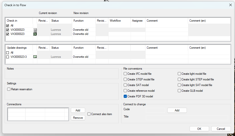
(1) Select the command File > Checkin.
-
Vertex G4 will open the dialog window Checkin to Flow.
(2) Accept the default options by selecting OK.
Switch to Flow's Browser Interface
(1) Select the model that was just saved to Flow.
-
It can be easily found under Archive > History.
-
The model is reserved for you.
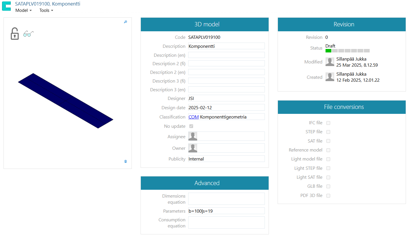
-
In the Advanced Information section, the Parameters field shows the variables related to the model, separated by vertical bars.
(2) From the 3D Model section, select Do Not Update.
(3) Restore the model's reservation by selecting the command Model > Restore.
Create a New Item
(1) Select
(2) Choose Items and Structures > Item.
(3) Select the category under which you want to create the new item.
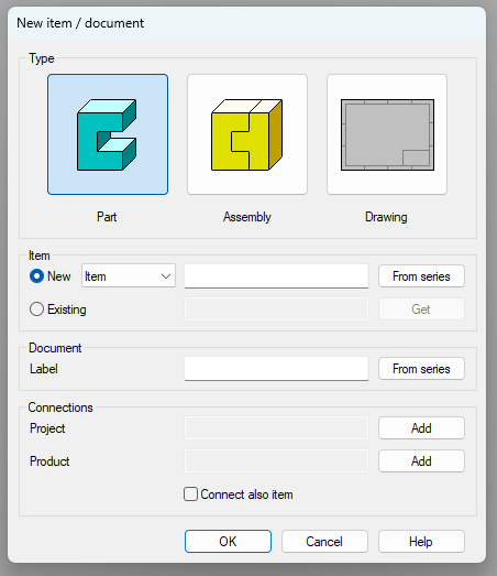
(4) Choose the contextual action New Item.
-
Flow will open the dialog box Add Item.
(5) Enter an identifier or retrieve it from the identifier series.
(6) Enter a description or retrieve it from the dictionary.
-
See: Using Dictionaries
(7) Select the unit of measurement.
-
The units of measurement are important for calculating the weight of components and raw materials.
-
For components, the unit is pieces (kpl).
-
For profiles, the unit is mm (or m). Vertex G4 provides lengths in millimeters, so use the unit mm.
(8) Fill in other fields as necessary.
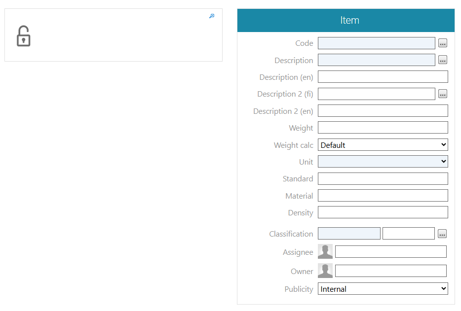
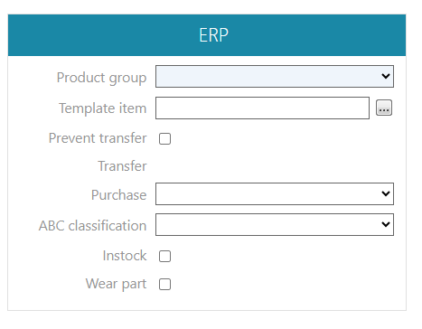
(9) Select the product group from the Production group section.
-
Material: This option is suitable for profiles.
-
Component: This option is suitable for components.
-
(Semi-finished Product)
-
(Product)
(10) Fill in or select other fields and selection blocks as needed.
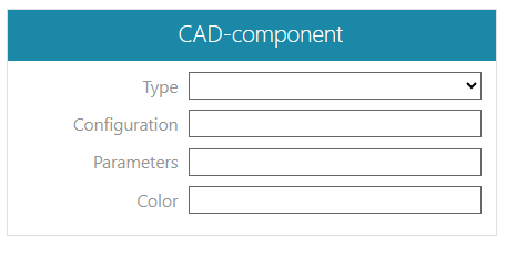
(11) Fill in the Parameters field in the CAD Component section.
-
The content of this field determines how the model associated with the item will be varied according to the item's dimensions.
-
Refer to the content format in the Parameters field of the Additional Information section of the model linked to the item.
(12) Select the type in the CAD Component section if necessary.
-
The field is left blank for profiles and conventional components in Vertex G4.
-
For components in 3D electrical design, selection is mandatory.
(13) Enter the appearance in the CAD Component section if necessary.
-
If the model associated with the item has multiple appearances and you want a different appearance than 0 (zero) that represents the item's geometry, enter the appearance number in the Appearance field.
(14) Enter the color in the CAD Component section if necessary.
-
If you want a color that differs from the model for the component or profile, enter the color code.
-
The codes for colors or visual surface materials can be viewed in the Vertex G4 user interface.
(15) Enter or select the content for other fields or selection boxes as needed.
-
In sales information, you can provide alternative spare part or sales descriptions that deviate from the standard for the item.
Attach a Model to the Item
A model must be attached to the item if it is used as part of a Vertex G4 assembly.
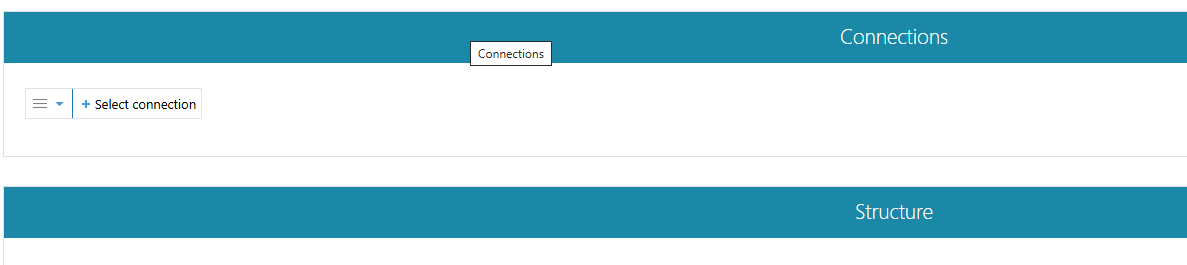
Using the Connections Section
(1) Click the Select Type button.
-
Flow will open a list of object types.
(2) Select Model.
(3) Click the +Select to Attach action.
-
The list will display the most recently processed models.
-
You can also type a string and search for a component or profile model based on its name.
Using the Connections Tool
(1) Select the action Tools > Connections > Add.
-
Refer to: Add Connection.
Copy an Item as a New Item
It is advisable to establish items related to the same model by copying an already linked item as a new item and then changing only the contents of the modified fields in the property information, such as the Parameters field in the CAD Component section.
(1) Select the item that is linked to the model.
(2) Select the action Item > Copy.
(3) Enter or select the identifier.
(4) Fill in the fields in the CAD Component section as described above in the Establish Item section.
-
At least the Parameters field requires new content.
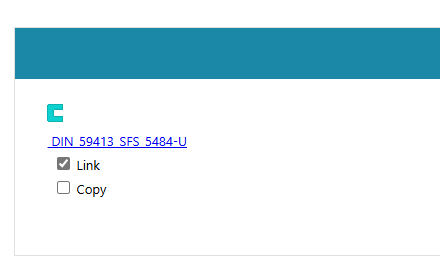
(5) In the Connections section, select the model and click Link.
-
This will ensure that the new item is linked to the same model as the item being copied.