
Create a new study
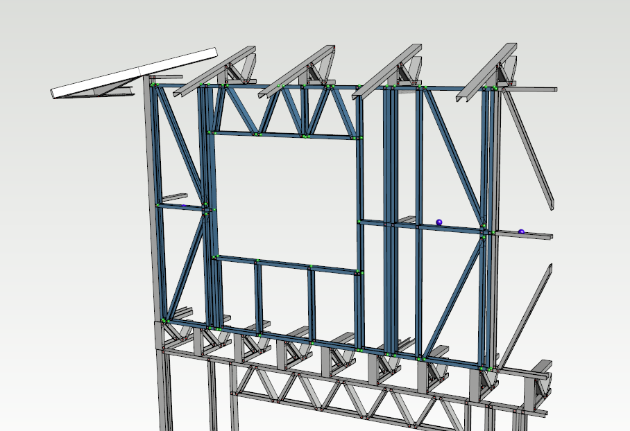
Select all wall panel members and create a new FEA study.
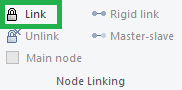
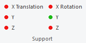
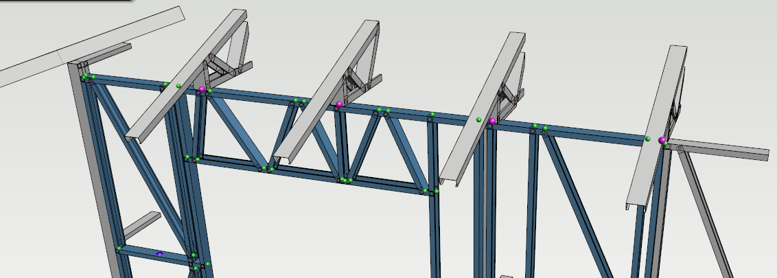
Linking nodes
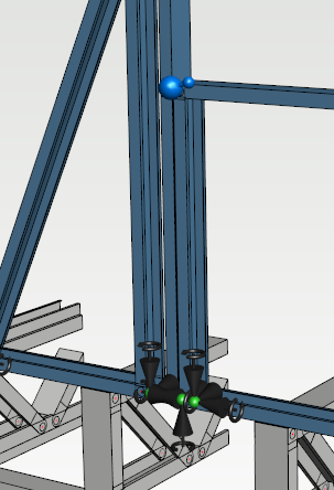
Parts which are locating near can be connected together using node linking. The first selected node is the master node and the second node is a slave node, master node is shown as a bigger blue ball object in the model. In this example two parallel studs are linked together near opening.
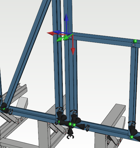
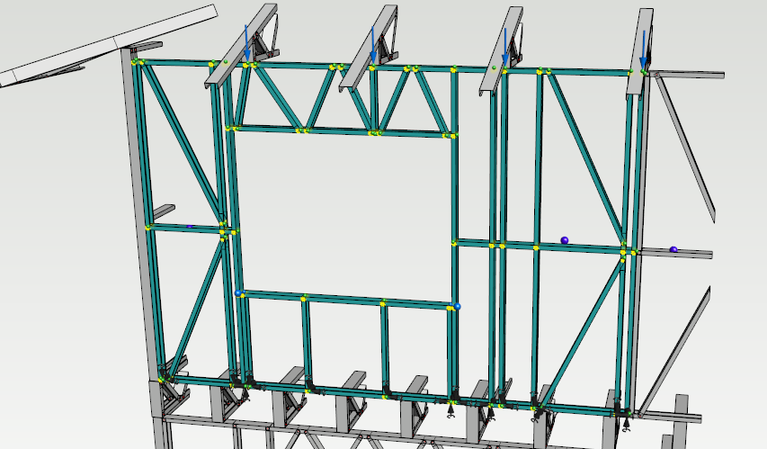
Set supports
Translations of stud's bottom nodes are locked when the bending of the bottom track is excluded in this study. Slave nodes cannot be used as supports.
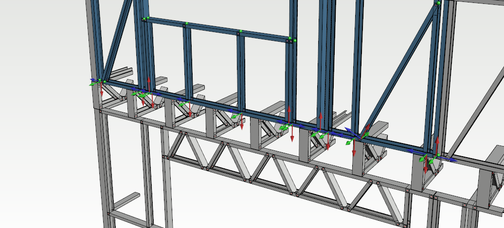
Select all nodes and set translations.
Locked translations are shown in the model.
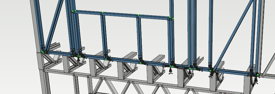
Add point loads
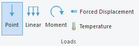
Select nodes for point loads
In this example truss loads are transferred to the wall panel using point loads. Point load values can be checked in truss design sheets.
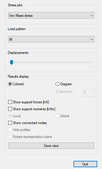
Check results
Select Solve function in the ribbon menu.
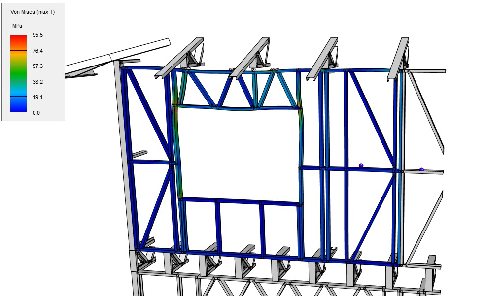
Capacity Check
Check the capacity of the structure by creating load patterns, setting buckling lengths for the members and running the capacity check.