
Before engineering the trusses, few connections need to be manually defined in order to transfer loads
-
Connections between trusses, jack trusses perpendicular to girder truss meet girder
-
Connection between panels, and panel to truss.
-
Hip slope/panel must be supported by an end wall / beam
-
Check member material, selected grade is used in engineering
-
Use joist hangers or direct screw connection between trusses to generate support relation between girder truss and trusses supported by girder. Connections must be correctly defined between truss/panel members.
Add Connection
-
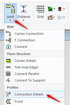
In ‘Modeling tab’ click on Joint icon → Connection Details
-
When working on a building model or drawing, you can pin

-
You can open a new browser from your opened browser by pressing

-
To activate this
-
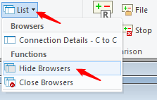
You can also hide pinned /opened browser/s. In View tab → List → Hide Browsers
Truss to truss 'Direct screw connection'
-
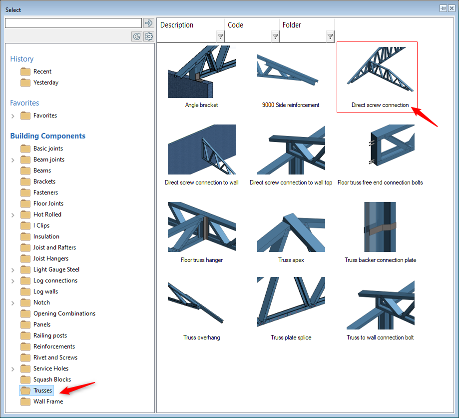
In the Select dialog box, select Trusses folder and click the ‘Direct screw connection’
-
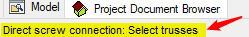
Pay attention to the instructions at the bottom left corner of Vertex window
-
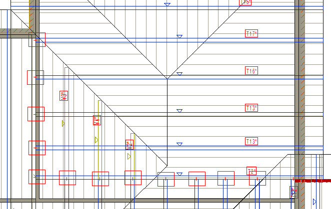
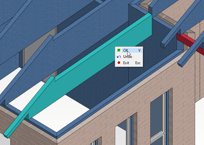
Pick a window around the ends of the trusses to be connected and the girder truss, Right click and confirm.
-
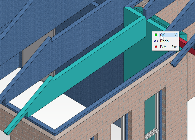
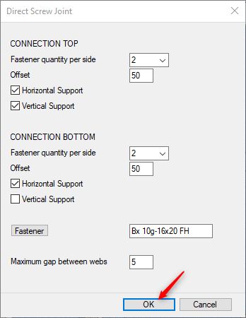
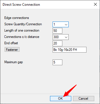
In 'Direct Screw Joint' dialog box', accept the defaults and click on OK.
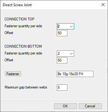
-
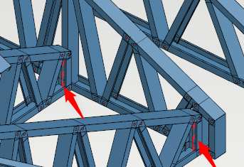
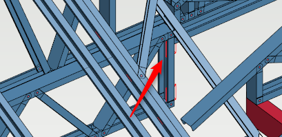
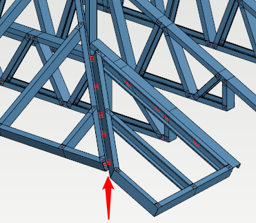
Trusses will have direct screw connection to the girder truss as shown
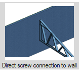
Truss to wall 'Direct screw connection to wall'
-
In the Select dialog box, select Trusses folder and click the ‘Direct screw connection to wall’
-
Pay attention to the instructions at the bottom left corner of Vertex window
-
Select the truss/s, right click and click on OK to confirm
-
Select the wall, right click and click on OK to confirm
-
In 'Direct Screw Joint' dialog box, accept the defaults and click on OK.
-
Truss will have a screw connection to the walls
Panel to truss multiple direct screw connection
-
In ‘Modeling tab’ click on Joint icon → Connection Details
-
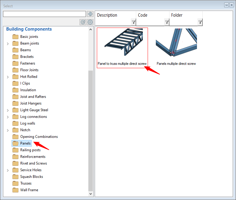
In the Select dialog box, select Panels folder and click the ‘Panel to truss multiple direct screw'
-
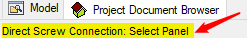
Pay attention to the instructions at the bottom left corner of Vertex window as shown.
-
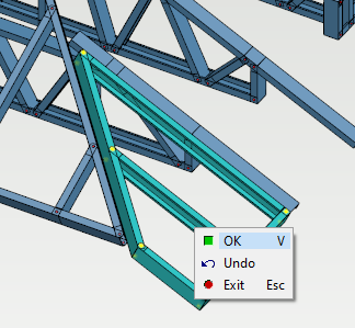
Select the panel, ( that need to be connected to the truss ) right click and click on OK to confirm
-
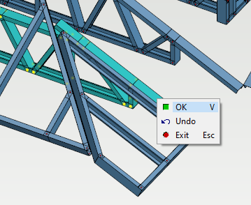
Select the truss ( the panel need to connected to ), right click and click on OK to confirm
-
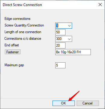
In 'Direct Screw Connection' dialog box, accept the defaults and click on OK.
-
Panel to truss multiple direct screw connection have been added
-
Follow similar process to add rest of the panel to truss connections.
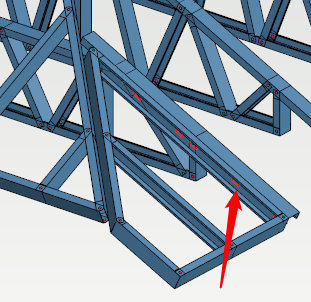
Panel to Panel or 'Panels multiple direct screw' connection
-
In ‘Modeling tab’ click on Joint icon → Connection Details
-
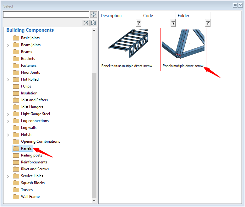
In the 'Select' dialog box, select 'Panels' folder and click on ‘Panels multiple direct screw'
-
Again pay attention to the instructions at the bottom left corner of Vertex window
-
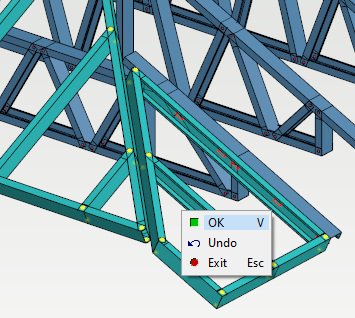
Select the panels that need to be connected to each other, right click and click on OK to confirm
-
In 'Direct Screw Connection' dialog box, accept the defaults and click on OK.
-
Panel to panel multiple direct screw connection have been added.
-
Follow similar process to add rest of the panel to panel connections.
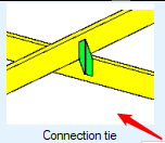
Connection tie can also be used in some cases to connect jack truss to corner jack truss, or hip panel rafter to truss etc.
-
In ‘Modeling tab’ click on Joint icon → Connection Details
-
In the Select dialog box, select Joist and rafter folder and click the ‘Connection tie'.
-
Follow the instruction at the bottom left corner of Vertex window. Connections must be defined correctly ( such as primary and secondary member ) between truss/panel members.