Switch to Ceiling Model pair :
-
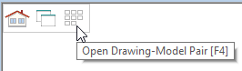
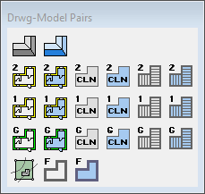
First we need to change to ceiling model pair, to do that we need to activate Drawing Model pair menu.
OR by pressing F4 key.
-
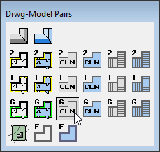
Select Ground Floor Ceiling model pair
-
In ground floor ceiling model pair all your wall geometry will not appear. In order to draw ground floor ceiling plane, you need to see ground floor wall perimeters, therefore either you can add ground floor walls as Reference drawing OR you can Set visibility of ground floor walls to ground floor ceiling model pair.
-
Generally you draw walls in the ground floor model pair. But you can make them visible in the Ceiling and roof model pair. That way, you don’t have to use reference drawings. ( You have to be careful that you don’t, accidently modify or delete them in other model pair )
Add / Load reference drawings:
-
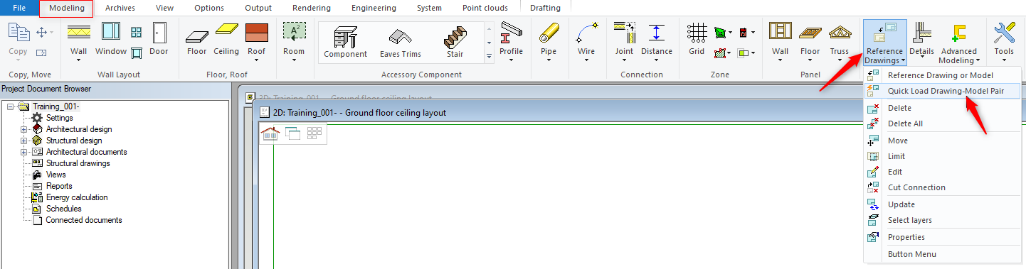
While you are in ceiling model pair go to 'Modeling' tab → 'Reference Drawings' icon and from the drop down menu click on 'Quick Load Drawing-Model Pair'
-
That will bring up ‘Drawing-model Pair’ menu.
-
Click on the model pair, that you want to use as a reference. In this case we can select ground floor wall layout
Set Visibility:
-
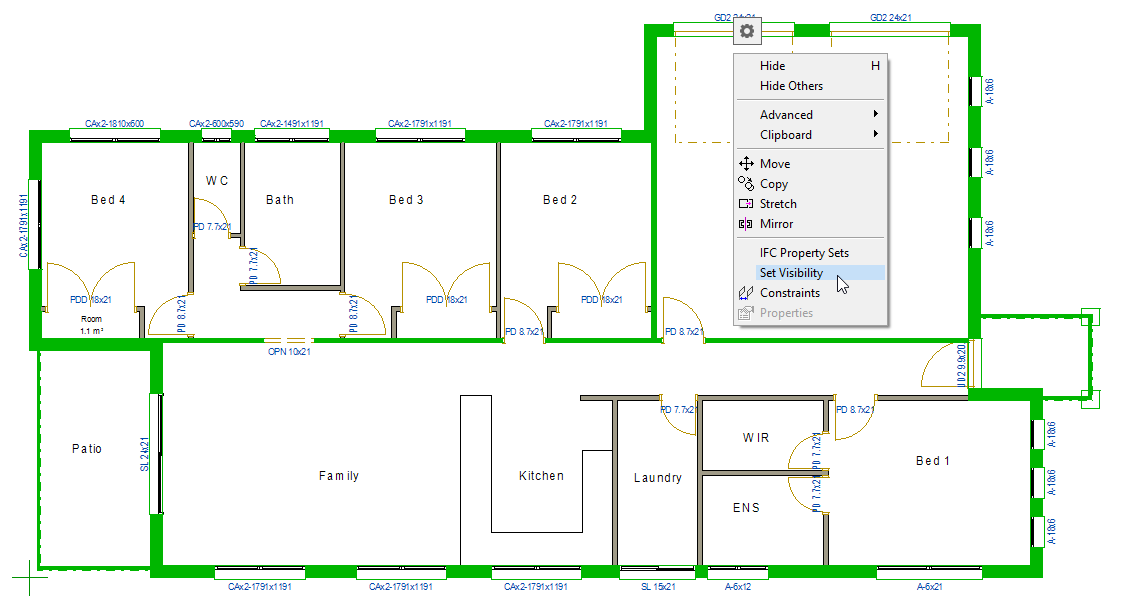
You can select an object or an item in both 2D & 3D ( Hold down the Ctrl Key to select more than one item/object ). Click right mouse button and form the contextual menu select ‘Set Visibility’. That will bring up ‘Select drawing-model Pair’ window on the left hand side of the screen. Tick the check box for the intended modal pair layout ( where you want selected objects to be visible ) and
don’t forget to click OK.
-
In this exercise we will select all external walls, beams, columns and two internal load bearing walls, right click and from the menu select Set visibility.
-
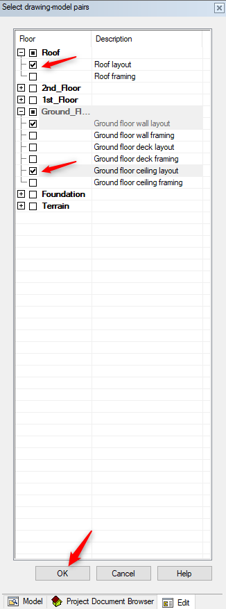
That will bring up ‘Select drawing-model Pair’ window on the left hand side of the screen.
-
Tick the check box for Ground floor ceiling layout and Roof layout as shown below.
-
Click on OK
-
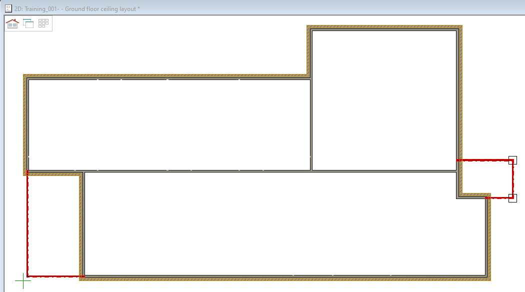
Switch to ground floor ceiling model pair, you will notice that the wall are visible now.
-
Now you are ready to add ceiling plane on the ground floor walls.
-
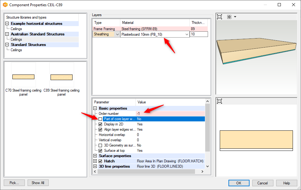
For roof truss engineering purpose, it is imperative to have a sheeting layer below ceiling plane to take the ceiling loads layer on to it.
-
Order number -1 OR if you have ceiling battens then the sheeting layers's order should be - 2
-
Part of the core layer can be unticked, since you don't want ceiling sheet to go over the wall
-
( if you leave Part of the core layer ticked, subsequently the wall height will be reduced by the thickness of the ceiling sheeting and ceiling sheet will extend over onto the walls )
Add Ceiling:
-
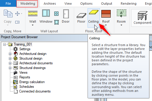
In Modelling tab click on Ceilings icon
-
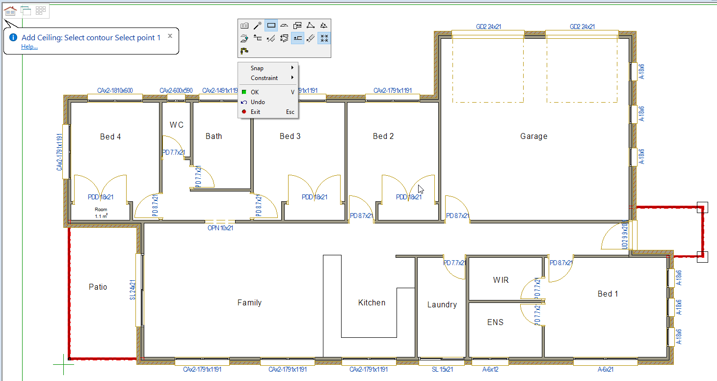
Right click on the screen and the Contextual menu pops up (shown below) that lets you select the ceiling area by points or by walls.
-
Pick the points of the outside face of the steel frame (clockwise), at the end right click and confirm or press ‘V’.
-
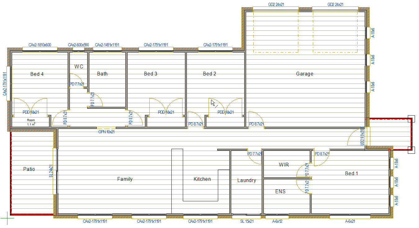
The ceiling will appear in this view.
-
Use F2 to change to the 3D view and check that the ceiling is at the right level. If it is not you can easily move it to the correct position.