
Switch to Roof Model Pair:
-
First, you must change to the drawing model pair by pressing F4 or selecting the drawing model pair from file menu and select Roof
-
In roof model pair all your wall geometry will not appear. In order to draw roof plane, you need to see ground floor wall perimeters, therefore either you can add ground floor walls as Reference drawing OR you can Set visibility of ground floor walls to ground floor ceiling model pair.
-
Generally you draw walls in the ground floor model pair. But you can make them visible in the Ceiling and Roof model pair. That way, you don’t have to use reference drawings. ( You have to be careful that you don’t, accidently modify or delete them in other model pair )
Add / Load reference drawings :
-
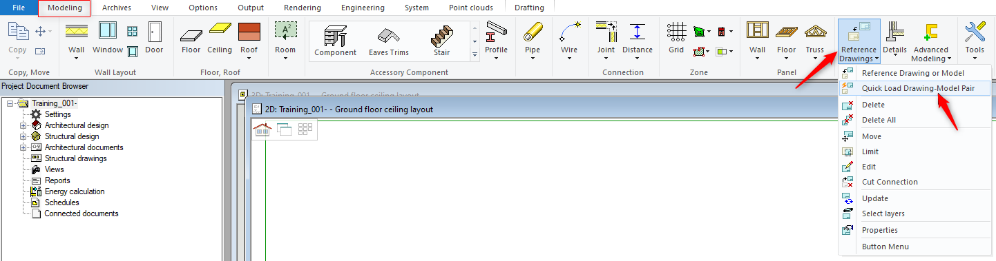
While you are in Roof model pair go to 'Modeling' tab → 'Reference Drawings' icon and from the drop down menu click on 'Quick Load Drawing-Model Pair'
-
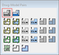
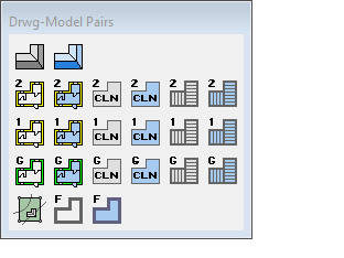
That will bring up ‘Drawing-model Pair’ menu.
-
Click on the model pair, that you want to use as a reference
Set Visibility:
-
You can select an object or an item in both 2D & 3D ( Hold down the Ctrl Key to select more than one item/object ).
-
Click right mouse button and form the contextual menu select ‘Set Visibility’.
-
That will bring up ‘Select drawing-model Pair’ window on the left hand side of the screen.
-
Tick the check box for the intended modal pair layout ( where you want selected objects to be visible ) and don’t forget to click on OK.
-
In this exercise we will select all external walls, beams, columns and two internal load bearing walls, right click and from the menu select Set visibility.
-
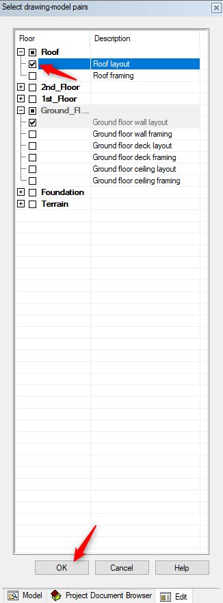
That will bring up ‘Select drawing-model Pair’ window on the left hand side of the screen.
-
Tick the check box for Roof layout as shown below.
-
Click OK.
-
Switch to Roof model pair and you will notice that the wall are visible now.
Combination of methods can be used to generate roof. As well as creating a regular Eave Line. Then use that eave line as a reference for the roof generator. You can add an eave line by using Points, Lines or walls.
Another method is Roof Generator, where you can generate an eave line and roof surface in one go.
ROOF Generator :
-
In this exercise we will generate an eave line and roof surface in one go. Surface can be manipulated and converted to the regular roof structure. You can add an eave line by using Points, Lines or walls
-
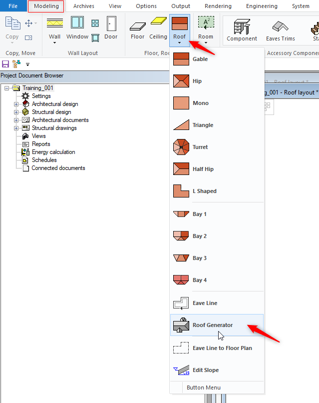
In ‘Modeling’ tab click on Roof icon select Roof Generator
-
Right click and the Contextual menu pops up
-
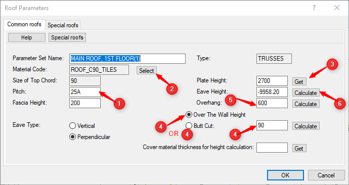
Click on ‘Truss’ and you will get a Roof parameters dialog box to define the parameters for the Roof

One of the important steps is that the user must select the material code, otherwise the roof panel will not be generated later.

Suffix A ( Angle ) must be there with the roof pitch value otherwise whole roof will be distorted.
ROOF Parameters :
-
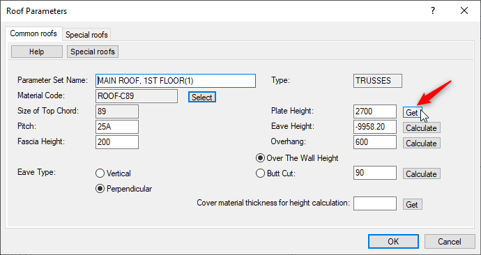
Check the ‘Pitch’ and ‘Fascia Height’ to make sure they are correct.
-
In this exercise we are using 25A degrees. Suffix 'A' must be there in Pitch field. A indicates angle / degrees
-
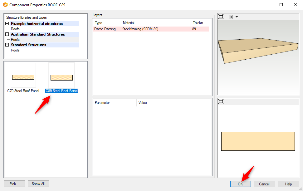
Click on Select button to right of Material code field ( as shown above )
-
This will bring up the Component Properties dialog box where you can select the roof material type.
-
Once you have selected the appropriate roof material type, click OK to return to the Roof Parameters.
-
Now click on the ‘Get’ button to the right of the ‘Plate Height’ field.
-
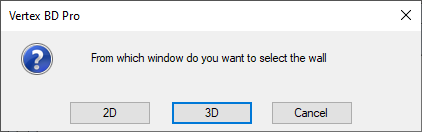
The program will ask which view, do you want to be in to select the wall. That will define the wall top plate height ( truss bottom cord will be sitting on it ).
-
Click on either one of the 2D or 3D option.
-
If you click on 3D option, it will take you into the 3D view. Select an External wall to define the correct height.
-
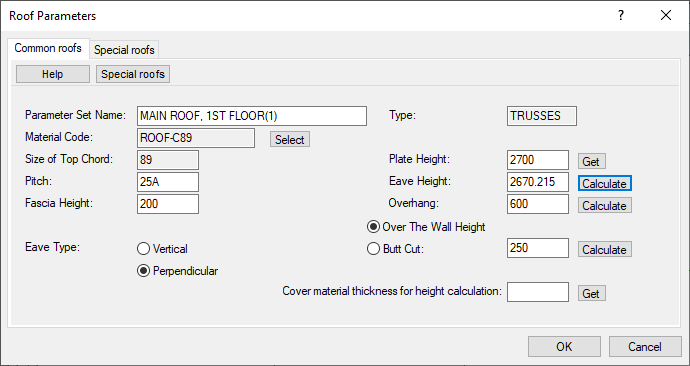
You will then be returned to the Roof Parameters automatically. You can see that the program has extracted the information from the selected wall to input the correct plate height field.
-
Choose either one of Over The Wall Height or Butt cut.
-
In this scenario we select Over the Wall Height to 250
-
Change the overhang to 600.
-
Click on ‘Calculate’ button to the right of the ‘Eave Height’ field and Vertex will calculate the correct height of the Eaves.
-
After Checking all the parameters click on OK.
-
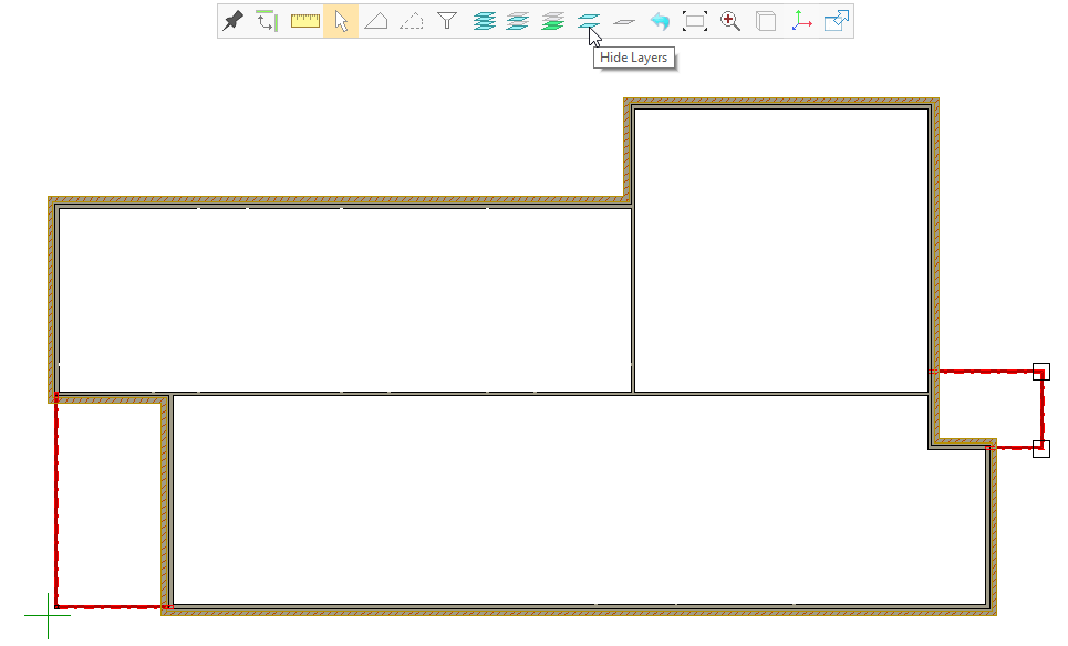
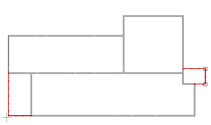
Note: 600 overhang we want from the wall framing not from the bricks. Therefore we need to hide brick layer.
-
Click on hide layers in tool strip and click on the brick layer directly.
`
-
Right click and select 'Add by line'
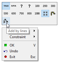
-
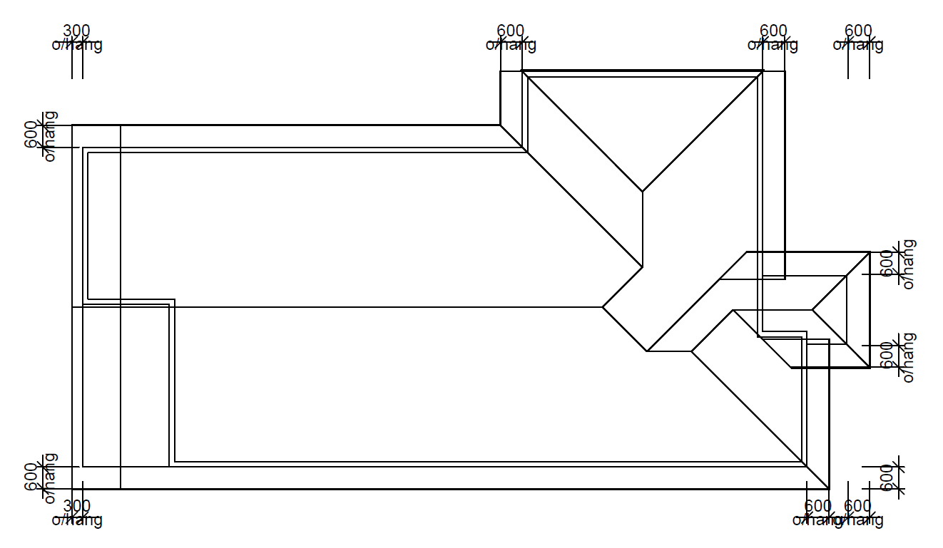
Now click on the every perimeter of external walls clockwise as shown
-
At the end right click and click on OK to confirm OR press 'V' on the keyboard to confirm.
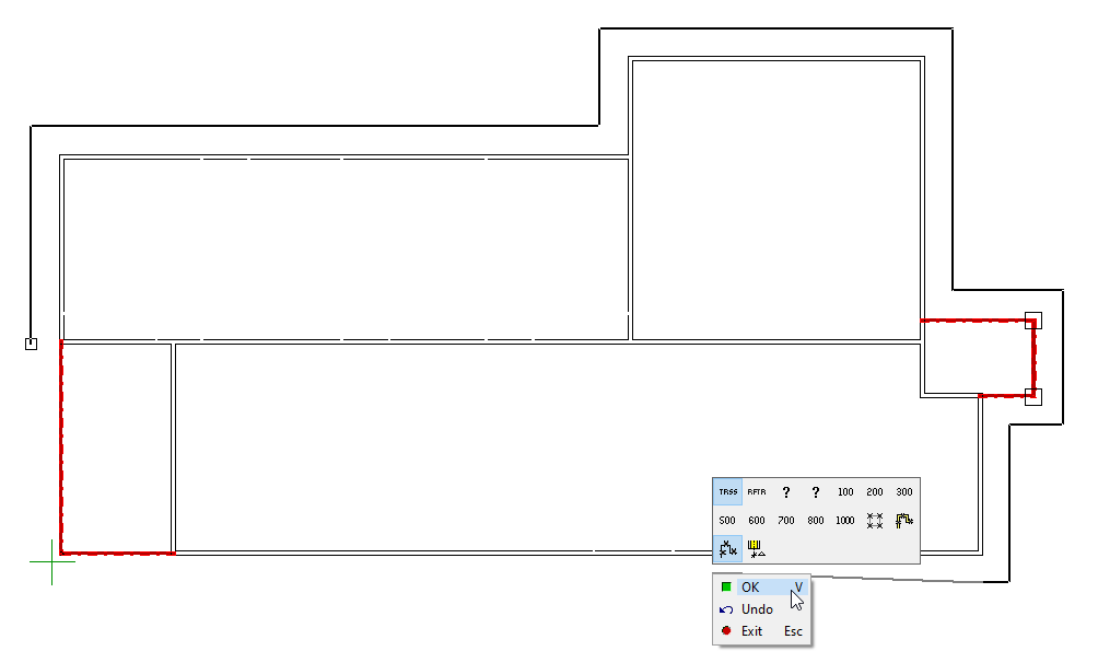
-
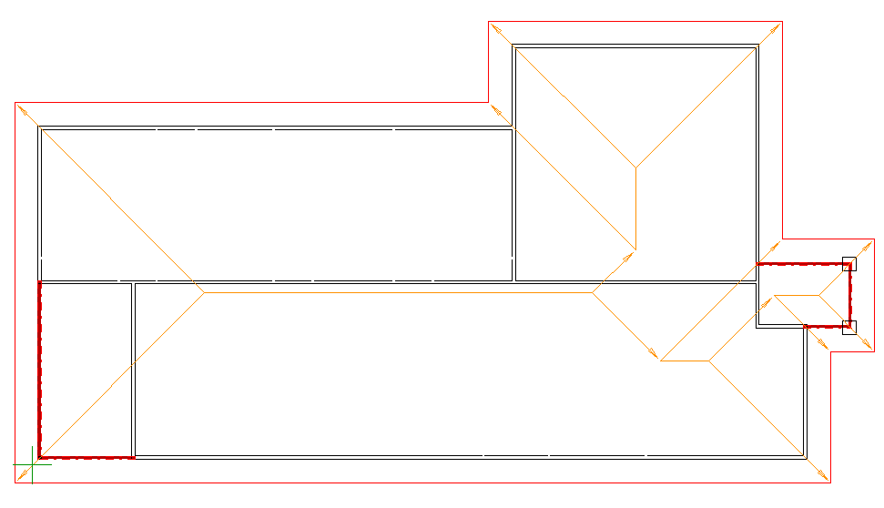
Now the roof shape lines have been formed as one go.
Converting Hip to Gable Roof:
-
Now we want to convert left hand side hip roof ( by the rear patio ) to gable roof.
-
Click on the Roof shape lines. All roof shape line turn green ( as shown )
-
Hover over or close to the coordinates (by the rear overhang) you will see this

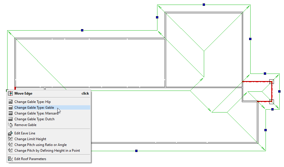
-
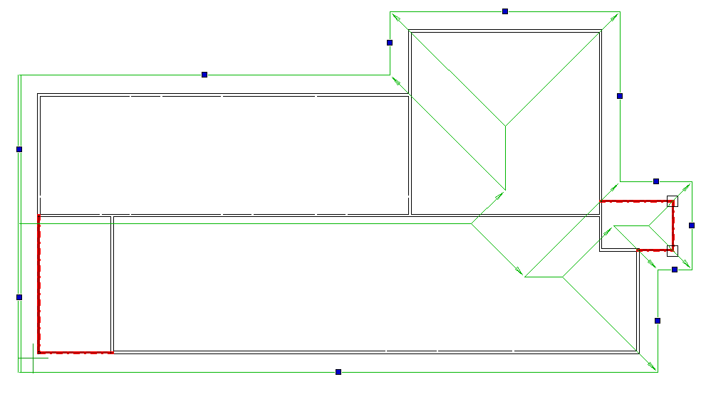
Left hand side Hip roof has been converted to Gable roof
Converting Surfaces to Roof:
-
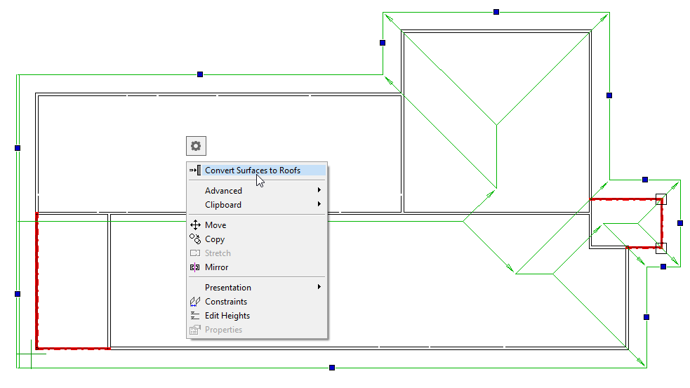
While the roof shape lines are already selected right click again and click on ‘Convert Surfaces to Roof ‘
-
Now the roof extents will appear in this view
-
Click on

-
Adjust the overhang to 300 on the left hand side of the building. Just by click on the roof plane. Now form the centre square coordinate point drag towards the right and type 300 then enter. Now the overhang at the left hand side of the building has been changed to 300mm
Clip (Cut) roof:
-
We can clip (cut) the roof to make Zero Overhang by the garage door.
-
First select the roof plane, 'Plane Structural' tab get activated.
-
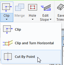
Click on Clip → 'Cut by Point'
OR
-
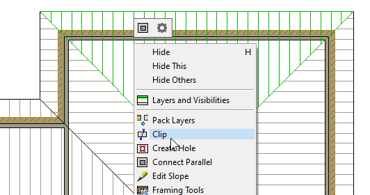
Right click and form the contextual menu select 'Clip'.
-
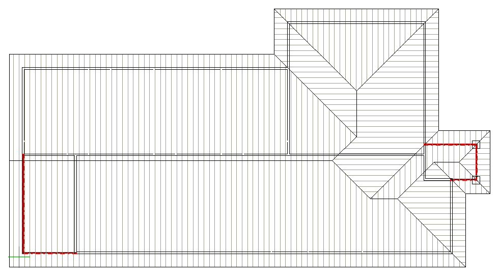
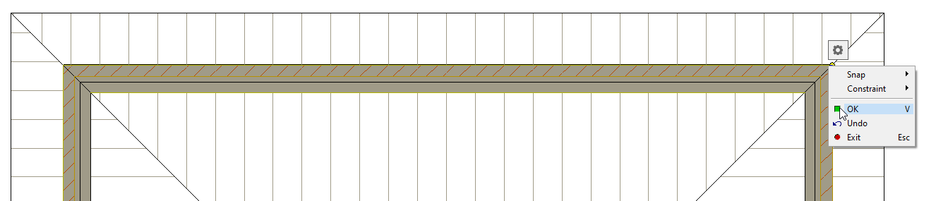
Select from left hand side of the Brick wall corner to the right hand side of the brick wall corner (as shown below) right click or hit V to confirm.
-
Delete the Cut-out overhang part of the roof.
-
Cut both end of roof with the same process.
-
Now you should have a roof that looks something like this
-
Press F2 for 3D view
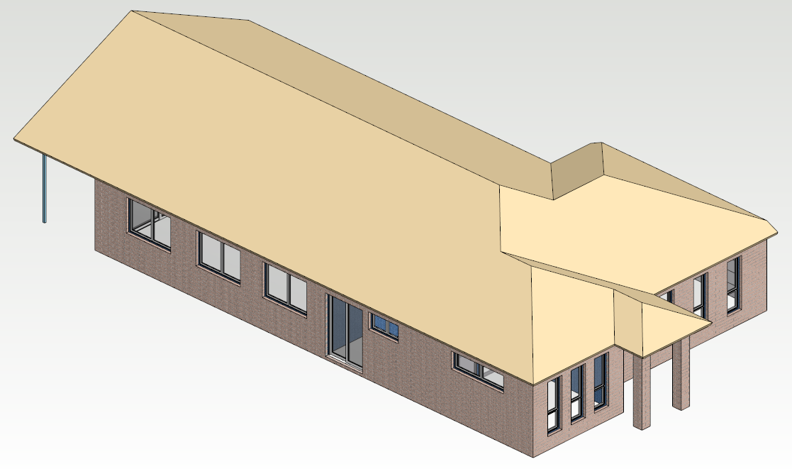
Raising Roof :
-
We are going to raise Entry roof height by 400mm and adjust the roof coordinates to form roof shape to suit.
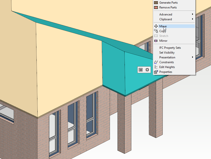
-
To raise the roof we need to be in 3D View. Select the roof (hold down ctrl to select more than one roof) that need to be raised. Right click and form the contextual menu click on Move. As you start moving upwards cursor changes to

-
Now just type 400 distance (as you type first number a little window pops as shown below ) and hit enter
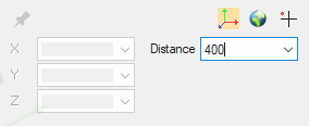
-
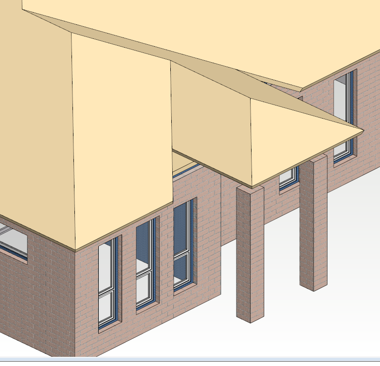
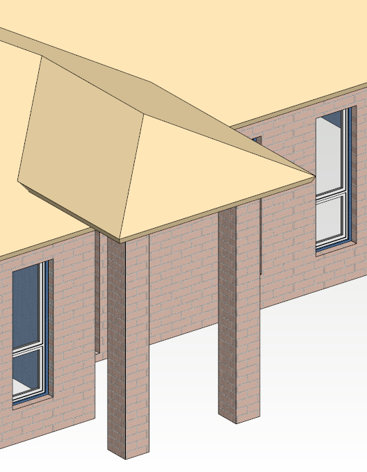
You will notice that apex of the roof is automatically adjusted
-
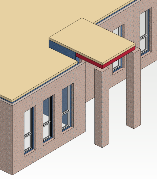
Since we are going to raise entry ceiling and the beams by 400mm.
-
We can cut/clip the ceiling (in 2D Ground Floor Ceiling Drawing Model Pairs) over the entry area by using clipping tool.
-
Also raise Entry Ceiling and Beams by 400mm (in 3D) as well as increase the Brick columns height (by Double clicking on the brick column edit height) by 400mm.
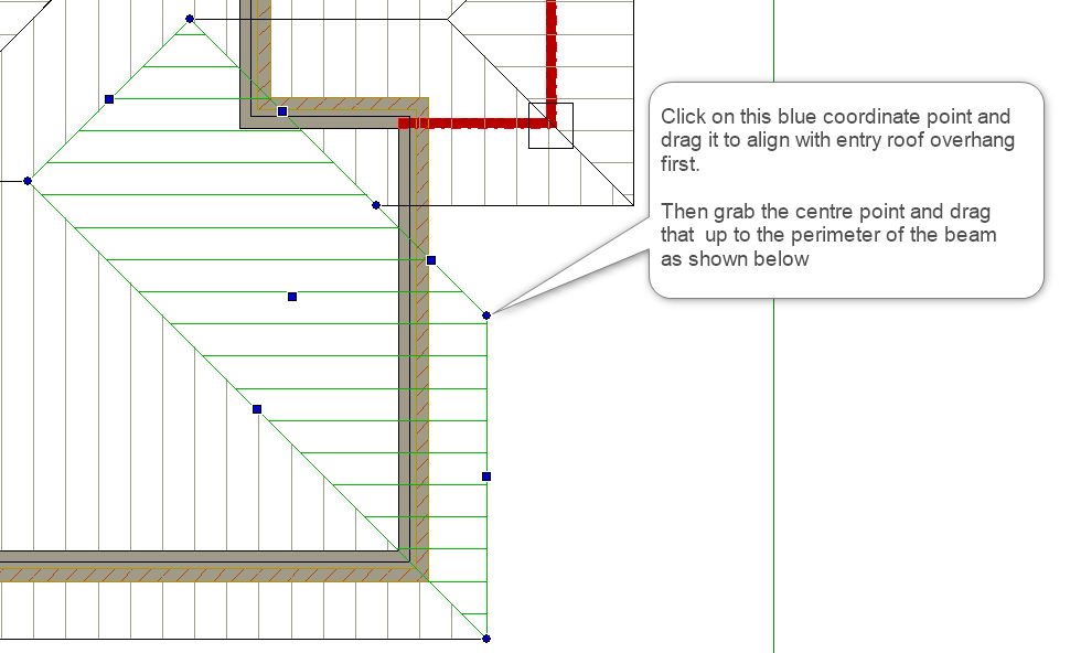
Add Roof point to adjust the roof :
-
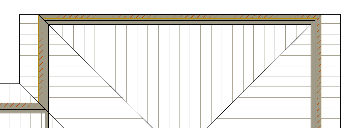
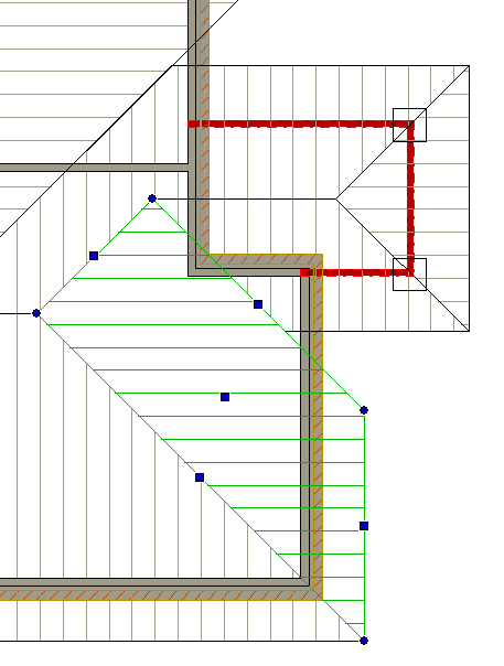
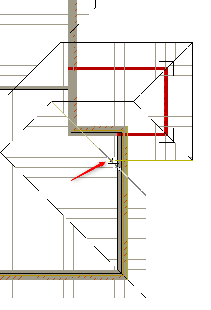
To adjust the roof overhang edges, we need to be in 2D view.
-
Select the roof plane, that need to be adjusted, the coordinates get highlighted (as shown ).
-
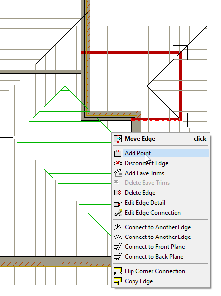
Hover over or near the centre ( square ) coordinate you will see this
-
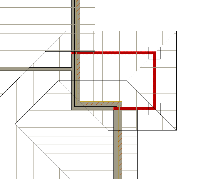
Click on the junction ( as shown ) and the point will be added to roof plane.
-
Now you will see coordinate points have been increased
-
Press 'F2' to switch to 3D view
-
Now we are ready to draw trusses