Use representations
The element mesh used in analysis is generated based on geometry of 3d model. The generation time of mesh is increasing significantly if geometry have many small details. In that case the use of representations is helpful. For example, detailed features can be hidden from a representation that is created particularly for FEA calculation. Features that have significant effect on mechanical behaviour of part should not be hided.
Use symmetry
If a part is symmetric it can be halved and run the analysis for only half of the part. This decreases the size of element mesh and calculation time.
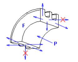
If a part is revolved the analysis can be done for a quarter of the part. The translation must be fixed in the normal direction of cut plane but other degrees of freedom must be free. Notice that the load values should be divided in the same ratio as part.
Example: In the figure below pressure P is affecting to a part F. Translational degrees of freedom are free in the directions of cut plane and fixed in the normal direction of cut plane. Fixed degrees of freedom are illustrated with red X symbol. In this kind of cases is useful to make representation of cut part.
Check integrity of geometry
The element mesh generation will probably fail if there are small gaps in 3d model. The mesh generation will also be difficult if the parts are connected to each other with edge or point. These details should be fixed to the model before running the analysis.
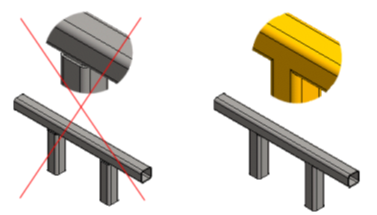
The analysis with solid elements (tetrahedron elements) is not suitable for profile and thin-walled structures. It is most suitable for machined and cast parts
Example: Trim profiles to parts to eliminate the gaps.