
Technical features
FEA for Solids and Assemblies supports linear static analysis for parts and assemblies. Boundary conditions and loadings are defined to surfaces of parts. Displacements and stresses can be solved by FEA analysis.
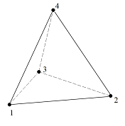
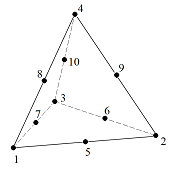
Types of finite element
Supported FEM element types of the analysis are 4 and 10 node tetrahedron elements. Their every node has 3 translational degrees of freedom. Tetrahedron elements can be stressed by tension and compression.
Material model
FEA uses linear and elastic material model.
Boundary conditions
Degree of freedom of surface can have three different states:
-
Fixed to connecting faces (free, if no connecting faces)
-
Free
-
Fixed at location
Surface can be defined as contact surface. Contact surface can not be penetrated inside its connecting faces but it can be separated from them.
Loadings
-
Force
-
Pressure
-
Forced displacement
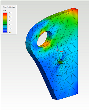
Results
Next stress types are solved in the analysis of solids and assemblies:
-
Von Mises stress
-
Minimum principal stress
-
Maximum principal stress
-
Normal stress on contact surfaces
-
Displacement
User interface
The user interface of FEA contains graphics of 3d model, study tree and ribbon menu commands. All commands are pointed into the active study. Passive studies are shown grey in the study tree.
Open the FEA state as follows:
-
Check that nothing is selected in the work window by pressing Esc.
-
Select from contextual menu FEA >


Return to the normal modeling mode as follows:
-
Select

-
Select

Modifications of 3d model is restricted in the FEA state.