
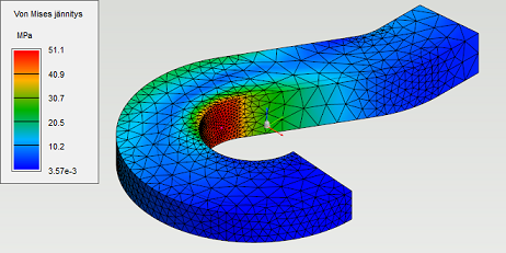
The parts of active study are meshed with 4 or 10 node tetrahedron elements. The density of element mesh have a great impact on results accuracy. In the area of more dense element mesh the results are more accurate. The drawback of dense element mesh is the increase in calculation time.
Read more about meshing plate structures with solid elements.
The impact on results accuracy is illustrated in the figures below.


Modify element mesh
-
Select

-
Modify element mesh with following functions:
Hide part
Parts can be hidden by hovering a mouse cursor over a part and pressing H.
Leave mesh visible
-
The element mesh can be left visible by turning on Leave polygon mesh visible setting. The element mesh is left visible when returning from FEA Mesh settings dialog.
-
The element mesh can be removed by pressing

Mesh settings - parameter descriptions
The influence of mesh settings is directed to all parts of active study.
|
Parameter |
Range |
Default value |
Description |
|---|---|---|---|
|
Type of tetrahedron element |
4 node, 10 node |
10 node |
Defines the used element type. With equal element meshes,
|
|
Relative target edge length [%] |
0-100 |
Surface: 20, Interior: 40 |
Defines the target relationship between individual element and geometry edge length. The target length is not always reached because of limitations caused by other mesh parameters. |
|
Maximum growth rate |
>1.0 |
Surface: 1.5, Interior: 2 |
Defines the maximum allowable growth rate between adjacent element edge lengths. |
|
Maximum spanning angle for curved surfaces [°] |
0-60 |
30 |
Defines the maximum allowable difference between the angles of adjacent element face normals in curved surfaces. With lower values the curved surfaces will have more dense element mesh. With large models (dimensions bigger than a meter) which have curved faces, decreasing this value often helps to improve the meshing result. |
|
Minimum edge length [mm] |
>0 |
0.5 |
Defines the minimum allowable length for element edge. This parameter is used to limit the element mesh density in small details like around small holes and near sharp corners. The minimum edge length is usually 1 or 2 orders of magnitude smaller than the absolute value of target edge length. |
Refine mesh
-
The element mesh can be refined locally around given point, edge or surface by pressing Target. Select point, edge or surface from 3d model and give target edge length for elements in millimeters.
Refinement around pointRefinement around edgeRefinement around surface