
The active study can be solved by pressing 
Change the stress plot
-
The presented stress plot can be changed from the buttons of Stress plot group in FEA results dialog.
-
Descriptions of different stress plots are listed in the table below
|
Stress plot |
Unit |
Description |
|---|---|---|
|
Von Mises stress |
MPa |
Stress value at node which is calculated from normal and shear stress components according to Von Mises yield criterion. |
|
Maximum and minimum principal stress |
MPa |
Maximum and minimum normal stress value at node when stress tensor is such position that shear stress components are zero. |
|
Displacement |
mm |
Displacement resultant. |
|
Normal stress |
MPa |
Normal stress component in the direction of surface normal. It is calculated only for contact surfaces. |
Examine nodal stresses
-
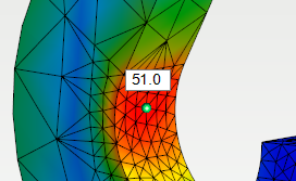
Nodal stresses and displacements can be examined by hovering a mouse cursor over examined node at 3d model.
-
-
When examining displacements following additional information is shown
Displacement components X, Y and Z in 3d model global coordinate systemThe gap value between contact surfaces when they are separated
-
-
-
The color of ball at the location of examined node gives information about state of the node contact
Green = node is on non-contact surfaceRed = node is on contact surface and it is fixed to connecting face in solutionBlue = node is on contact surface and it is separated from connecting face in solutionYellow = node is on contact surface and its contact state is about to be changed to the next iteration round
-
Examining nodal stresses is possible only when displacements slider is dragged all to the left.
Visualize displacements
-
The displacements of structure can be visualized by dragging Displacements slider.
-
The displacements of structure is shown in 3d model.
The visualization of displacements is not shown in real scale. The displacements are shown exaggerated.
Modify the visualization of results
Leave mesh visible
-
The element mesh can be left visible by turning on Leave polygon mesh visible setting. The element mesh is left visible when returning from FEA Mesh settings dialog.
-
The element mesh can be removed by pressing

Save view
-
The results view can be saved by pressing Save view. The background color can be changed to white if wanted.
Solving contact problems
If study includes multiple parts and contact surfaces are defined between connecting faces of parts the solution will be iterative. This means that analysis is performed multiple times as iteration rounds. Between iteration rounds the normal stresses of contact surfaces are examined. If the contact surface node has compression it will be fixed to the connecting face at next iteration round. Accordingly, if the contact surface node has tension it will be freed from the connecting face at next iteration round. When less than 5% of boundary conditions of contact surface nodes have been changed between iteration rounds the iteration will be terminated and the solution is reached.
The iteration of contact problem can be terminated at any point by pressing Esc. In that case the results are shown from the iteration round just before termination.
If the solution for contact problem has not been reached until ten iteration rounds the results of analysis can not be considered reliable! Iteration will be terminated automatically after ten rounds. If iteration is not terminated before ten rounds check the validity of support and contact boundary conditions.