

Exercise 6: How to generate isometric drawings
The main objective of this exercise is to add a special isometric symbol to the pipeline, fill in the pipeline data and generate the isometric drawing.
The estimated time to complete this exercise is 10 minutes.
This exercise was carried out with Vertex G4Plant 31.0 (2025).
In this exercise, you will learn to
-
How add isometric special symbols to your pipeline model.
-
Fill the line position data to the database.
-
How to generate isometric drawing and register the isogen module if needed.
-
How to "read" isometric drawings.
Functions in use
-
Isometric special symbols
-
Item Data > Lineposition > Line position data
-
Isometric of selected position
-
Save
Open the model of your main assembly
-
Open the model of your main assembly (EXP-MAIN.vxm) from the previous exercise.
-
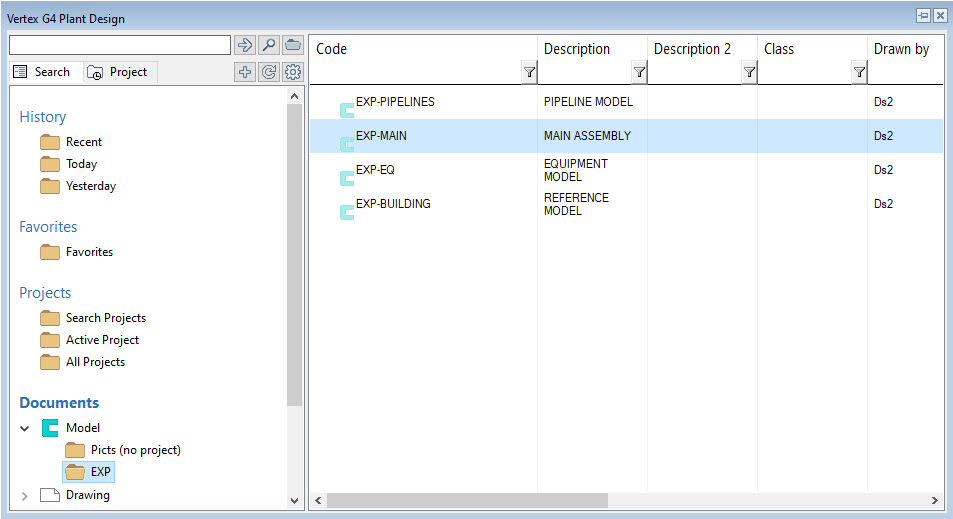
Open the basic browser by pressing B and find the segment Documents.
-
The segment Documents divides into two main branches Model and Drawing.
-
Search the folder of your project from the branch Model. Then double-click it to open the model.
-
You can find more information about the browser here.
Isometric special symbols
It's possible to insert so-called isometric special symbols into the pipeline. With their help, more information can be shown in the isometric drawing. A few examples of these special symbols are a flow arrow and split point. We will insert one special symbol into the pipeline in this exercise. This symbol will add a distance of a specific point to the nearest gridlines in the XY plane.
Edit the pipe model
-
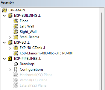
Select the pipe model (EXP-PIPELINES) from the assembly tree.
-
Context-sensitive function: Edit or double-click the sub-assembly from the assembly tree.
-
You are now at the editing state of the pipe model. You can see the symbols of other assemblies as unsharp in the tree. The symbol of the model you are editing is sharp in the tree.
How to insert isometric special symbol
-
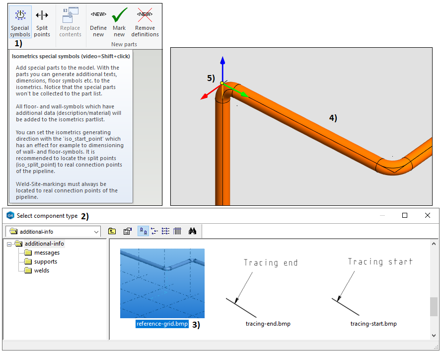
Tab Isometrics > Function Isometric special symbols, in picture 1).
-
The window Select component type opens, in picture 2).
-
Select the symbol type reference-grid.bmp and double-click it, in picture 3).
-
Next, Digitize pipe > Choose the straight pipe segment near the pump which has the elevation 3300 mm and it goes in the direction of the x-axis, in picture 4).
-
Then define the location of the symbol from the corner of the elbow like in picture 5).
-
Context-sensitive function: Exit.
-
The program inserts a local part called Reference-Dimension into the assembly.
-
You can insert other special symbols to the assembly with this method if you like.
Pipeline's data
The pipeline data is visible in the isometric drawing's title block if you have entered the data into the database. Some examples of this data are flowing material, insulation, and tracing data.
-
The model EXP-PIPELINES must be at the editing state.
-
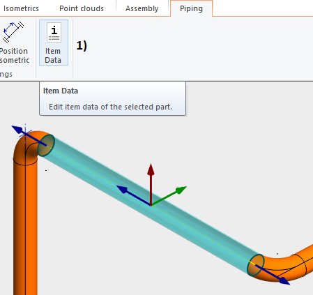
Select one of the pipe components > Tab Piping > Function Item data, in picture 1).
-
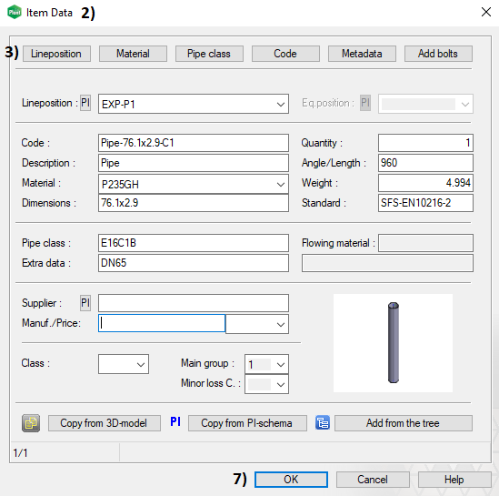
The window Item data opens that shows you the data of that specific pipe component, in picture 2).
-
Click the button Lineposition, which is on the top left corner, in picture 3).
-
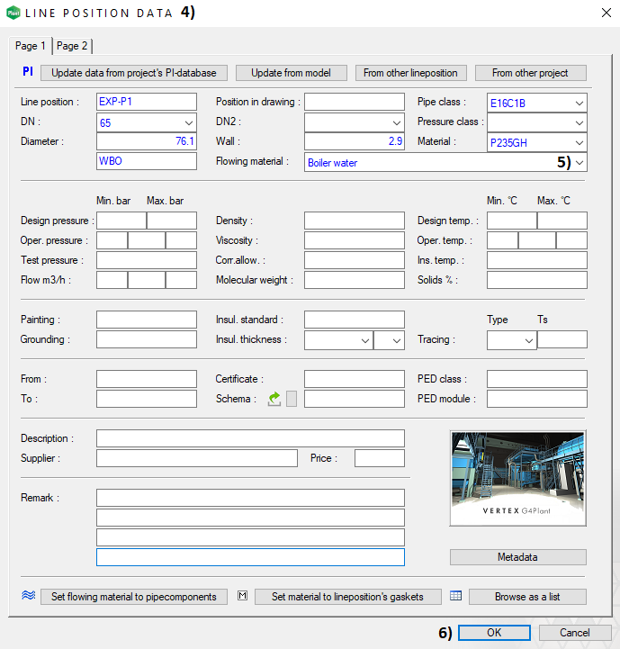
The window Line position data opens. The program automatically fills some of the fields, in picture 4).
-
Select Flowing material from the drop-down menu, in picture 5) > The window Flowing materials opens > Select first the group 6 Water, condensates from the list on the left > Select the flowing material Boiler water - WBO from the list on the right > Finalize by clicking the OK button.
-
Fill other process data to the fields manually or by using the drop-down menus if you like > Close the window Line position data when you are ready by clicking the OK button, in picture 6).
-
The line position data is now saved to the database.
-
Close the last window Item Data by clicking the OK button, in picture 7).
-
Return to the main assembly level on the model > Context-sensitive function: OK. This action will save the changes of the sub-assembly to the archive.
Generating isometric drawings
-
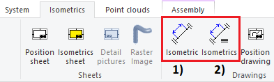
You can start generating isometric drawings either from the tab Assembly or Isometrics.
-
The third option is to select one pipe component from the line and then use the context-sensitive function: Pipe system > Create isometric of position.
-
You can create the isometric drawings one by one or multiple drawings with one command:
-
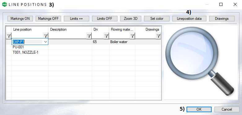
Tab Isometrics > Isometric of selected position > The window Lineposition opens, in picture 3).
-
Select the lineposition EXP-P1 >You can modify the lineposition data by clicking the button Lineposition data, in picture 4).
-
The program starts to generate the iso drawing after you have chosen the line position and clicked the button OK, in picture 5).
-
The isogen module requires registration before you can generate the drawings. The registration starts automatically when you run the first isometric drawing.
-
Answer Yes to the registration question!
-
The registration requires local admin rights to your workstation. Please see more detailed instructions here.
-
After the registration is completed, the program generates first the position drawing and then the actual isometric drawing.
Position drawing
-
The program saves the position drawing to the archive with the label I-EXP-P1_i00 when the default settings are active.
-
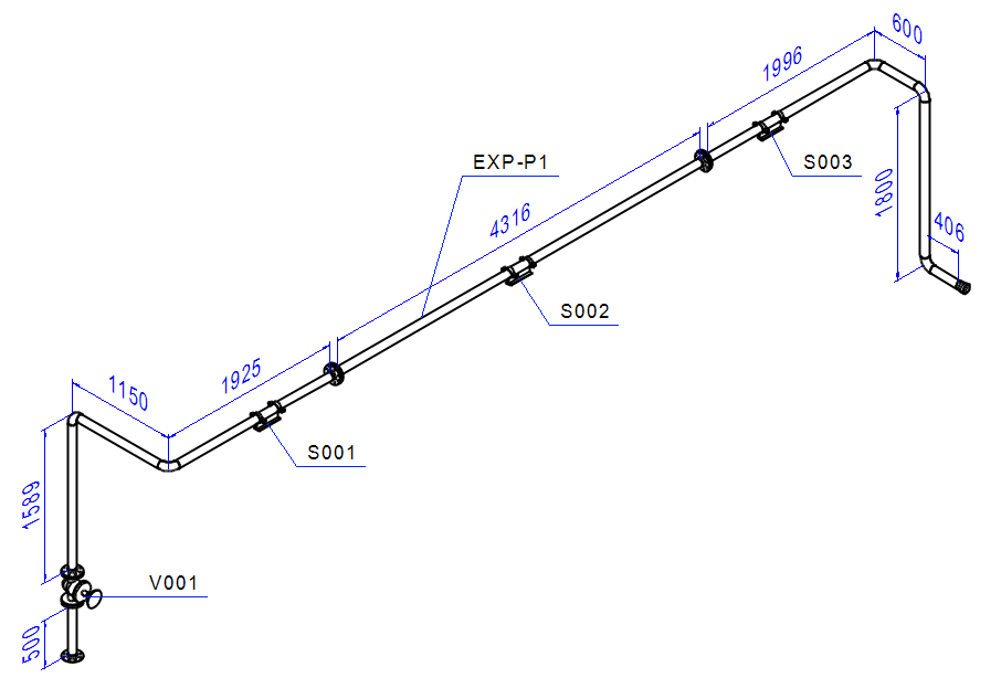
The position drawing shows an axonometric view of the pipeline so that the proportions are realistic.
-
When using the program's default settings you can see dimensions, line position, and equipment positions in the drawing.
-
The pipeline data is visible in the position drawing's title block if you have entered the data into the database.
Isometric drawing
-
The program saves the isometric drawing to the archive with the label I-EXP-P1_i01 when the default settings are active.
-
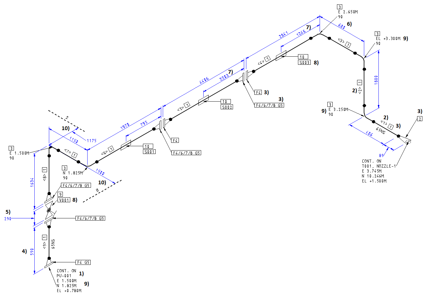
The isometric drawing shows an actual isometric, parts list, cutting list, and title block.
-
The pipeline data is visible in the title block if you have entered the data into the database.
-
The so-called wire representation is not true in scale.
-
Details of the isometric drawing:
-
Dimensions: There are many dimensions in the drawing,
-
From a sealing surface of a flange to another flange's sealing surface. The gasket's width is not taken into account, in picture 4).
-
The length of a pipe component. The gasket's width is not taken into account, in picture 5).
-
Distance between two elbow corner points (from corner to corner), in picture 6).
-
Support's place, in picture 7).
-
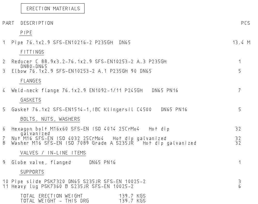
Parts list of isometric drawing
-
The parts list shows a part number, name, and quantity for each pipe component.
-
The program divides the list into groups with the default settings.
-
The name of the pipe components consists of multiple pieces of item data.
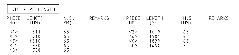
Cutting list of isometric drawing
-
The cutting list shows an identifier number, length, and size for each pipe segment.
Isometric drawings in the archive
-
The program saves the drawings automatically into the archive when the default settings are in use.
-
You can close the drawings after you have reviewed them.
-
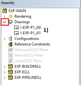
The program adds the drawings to the assembly tree when you generate the iso drawings with the function Isometric of selected position, in picture 1).
-
You can also generate the iso drawings when you are editing the model EXP-PIPELINES. Then the drawings are under that model in the assembly tree.
Save the model
-
Return to the main assembly level on the model > Working window > Right mouse button > OK. This action will save the changes of the sub-assembly to the archive.
-
Save the main assembly also: File > Save or click


You can download here the result of exercice 6 (EXP.vxz). (2 798 KB)
This transfer package will create a project EXP and insert models, drawing, and other files into the archive.
We don't recommend using this package if you already conducted the exercise by using the same labels for the project and models as guided.