Rendering
Adjust selected part appearance in assembly
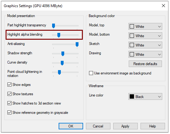
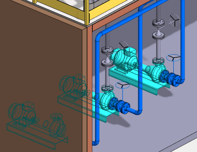
Now you can adjust how the selected part of an assembly is highlighted.
-
See the following figures.
-
File > User Preferences > Graphics.
-
With the slider you can adjust the value 0 ... 100%.
Value: 0%
-
The hidden part is not shown at all.
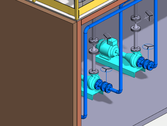
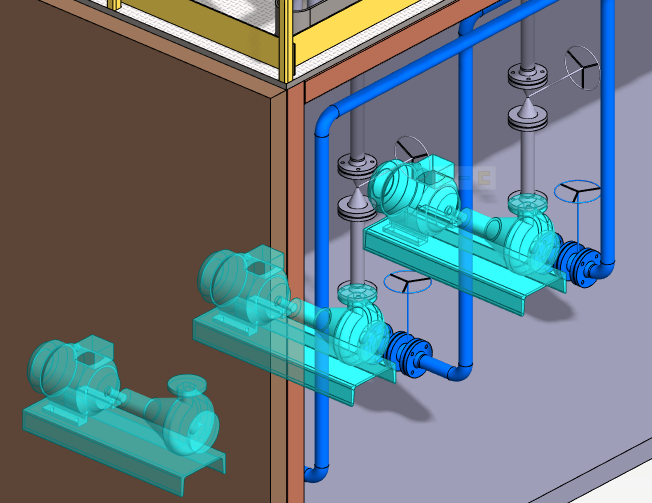
Value: 1%
-
The outlines of the hidden part are displayed.
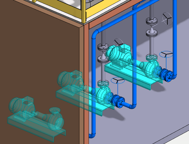
Value: 25%
-
The surfaces of the hidden part are exposed. Part covers 25% of the visible geometry.
Value: 50%
-
The surfaces of the hidden part are exposed. Part covers 50% of the visible geometry.
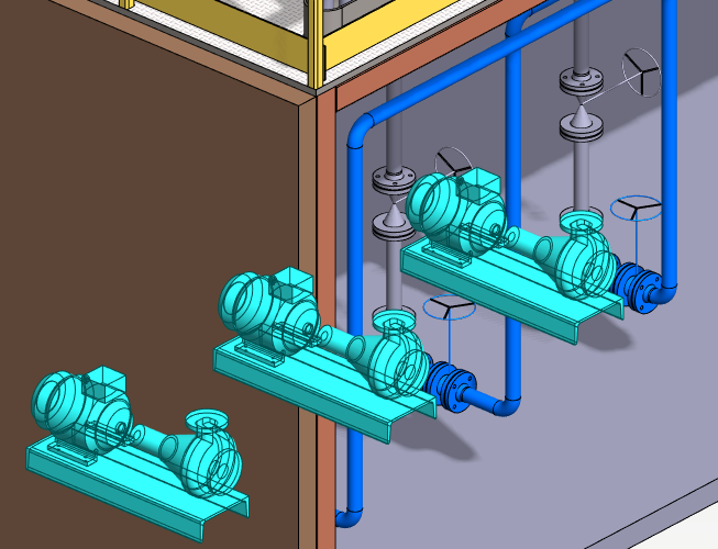
Value: 100%
-
The hidden part is rendered in the same way as the visible part. That is, the part completely covers the geometry visible in front of it.
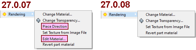
Editing of the rendering material is only possible in the part model
When a part or parts have been selected in the assembly that have rendering material assigned to them in the assembly, unlike before, the context-sensitive rendering menu lacks the Paragraph Orientation and Edit Material functions.
-
Inoperative features were already removed in version 27.0.08.
G4 - Flow
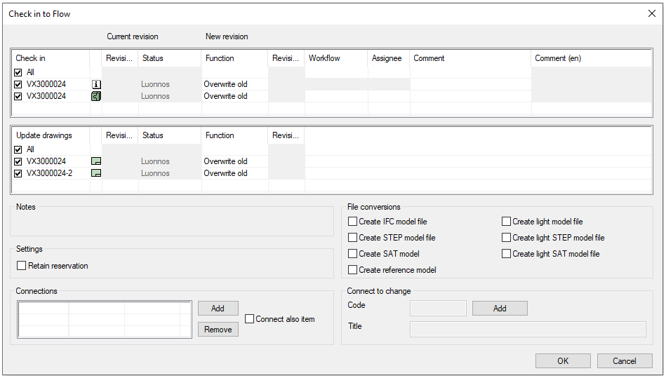
Update of drawings in the background
It is now possible to leave the update of the working drawings of the models to the Flow background converter. This is useful when updating drawings of large models (including plant layout models) that may reserve workstation's Vertex G4 program for several minutes.
See more on Flow's page: Background Update of Drawings 2022
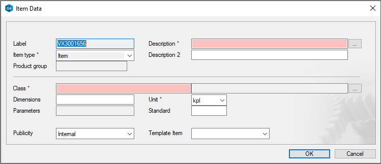
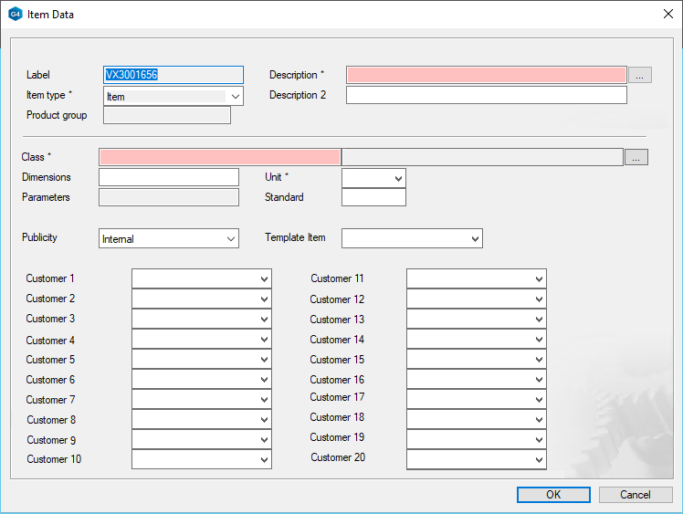
Up to 20 customer-specific fields for the item are now displayed
Previously, a maximum of 9 fields added to the item object by the customer in Flow were displayed on the Vertex G4 item card. Now that number has been raised to 20.
-
The item card appears in Vertex G4 when you create a new item and associated model or drawing.
Remember that after creating a item, you can only edit item's information in Vertex Flow and not in Vertex G4.
Default Item card if the customer has not added their own fields to the title
Item card with the maximum number of (20) customer-specific fields displayed on the Vertex G4.
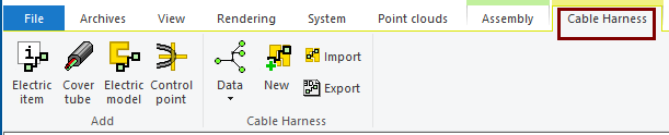
Cable harness design
General
Functionalities require the option of 3D Electrical Design for the Vertex G4.
There is a separate tab for 3D design of the Cable harness
-
In the assembly model, the tab opens next to the Assembly tab and contains the functionalities needed for 3D design of the wiring harnesses.
New settings
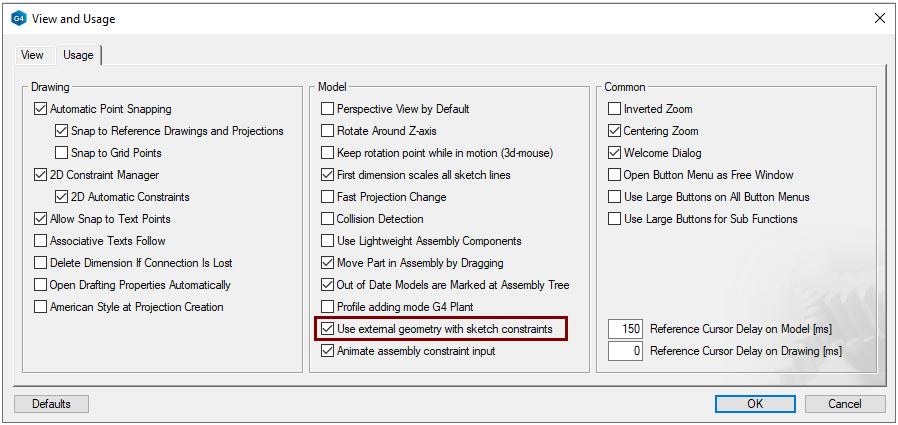
If necessary, align the sketch constraint with the geometry of an other parts
The program allows the geometry of other parts to be the second element to the constraint of the sketch. If you do not want the skects constraints to apply to the geometry of other parts, deselect the option.
-
File > User Preferences > Drawing, Models > Usage-tab > Model-group > Use external geometry with sketch constraints.
More on the page: Part modeling 2022
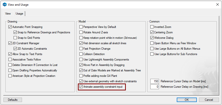
Rotate the parts of the assembly animatedly to the position indicated by the constraint
The program moves and flips parts animated by default when constraint are given in the assembly. The animation takes 0.3 seconds. If this delay bothers you, disable the animation so that the motion is not animated.
-
File > User Preferences > Drawing, Models > Usage-tab > Model-group > Animate assembly constraint input.