


Sketch
Use the geometry of the other parts for the constraints of the sketch.
You can more easily attach the constraints of the sketch geometry to other parts of the assembly.
Starting point: You are editing part of the assembly and making a sketch. Now, if necessary, the geometry of the other parts is available in constraints of the same way as the part's own geometry.
-
Sketch a line that starts or ends with the geometry (point or line) of other parts, and the program adds an automatic coincidence constraint between the end point of the line and the geometry of the other part.
-
Add a constraint between the geometry of the sketch and the geometry of the other part. First select to the geometry of the sketch itself and then to the geometry of the other part.
Decide if you want to use the geometry of other parts, such as the part's own geometry in the sketch constraints:

-
The functionality is available in both the 2D sketch and the 3D sketch when you edit a part of the assembly.


Functionality in older versions (27.0.xx or Vertex 2021 and earlier versions):
-
In the 2D sketch, no constraints were created automatically. If you wanted a constraint between the sketch lines and the geometry of the ohter part, then you had to first copy the line of the other part to the sketch (as auxiliary geometry) and add the constraint after that.
-
In a 3D sketch, when sketching a line, the constraint was always automatically generated in the geometry of the other part.
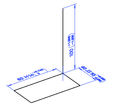
Add tolerated dimensions to the 3D sketch
We introduced the sketch tolerances in Vertex G4 version 25.0 (Vertex 2019). At the time, they concerned the dimensions of 2D sketches. Now you can also add tolerated dimensions to the 3D sketch. From the 3D sketch, you can use it to get a tolerated dimension to the extrusion length as well. This is accomplished by extruding a 2D sketch to a point in the 3D sketch.
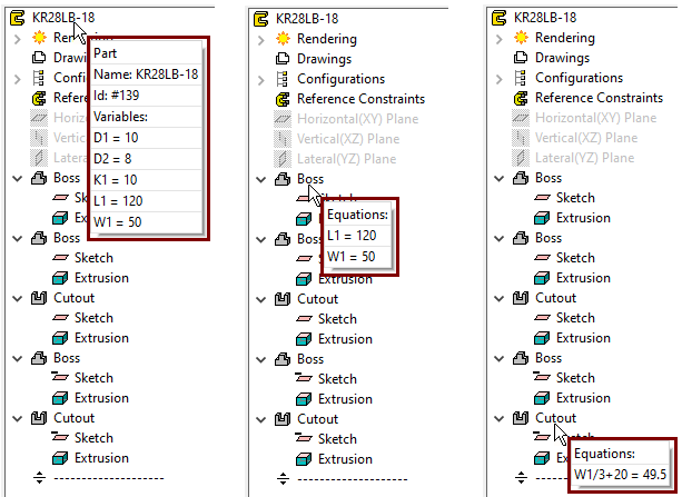
You can see the part and feature formulas without opening the feature
Move the cursor over the feature. If there are variables or formulas in the feature sketch or operation, then the program displays them as tip texts.
-
Next to the part symbol, you can see all the variables with their values.
-
For a feature, you can see the variables and formulas associated with the feature and their values.
The non-driving dimensions of the sketch are updated in real time
The program now draws the dimensions even as you drag from sketch. If the sketch geometry has non-driving dimensions, then the dimension is now updated in real time.
Until version 27.0.XX, no dimensions were drawn at all during drag.
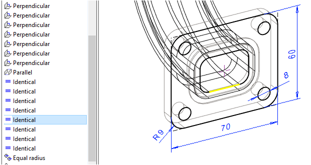
The identical constraint is now also displayed in the geometry
The identical constraint is created automatically when a line of geometry is copied to a sketch. Previously, the line has not been marked in the graphics window when the identical constraint is selected in the feature tree. Now, the line with the identical constraint is highlighted with color when it is selected from the feature tree. This helps in cases where the identical constraint needs to be removed from a particular line.
This feature was already introduced in version 27.0.03 (February 2021).
The line type of the rounding inherits its properties
Rounding line type inherits line properties from adjacent lines if they have the same line type. Previously (vers. 27.0.XX and older) rounding was always added to the sketch as a shape line
-
This caused unnecessary work if rounding was done, for example, at the fold of the contruction lines.
Adjust the transparency of the part in sketch mode
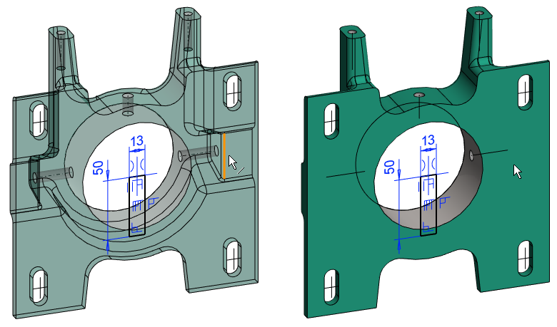
With the Transparent when Shaded sketch option, you can choose whether or not to display a part as transparent in sketch mode.
-
If you select transparency, the cursor finds the lines behind the sketch plane when you draw the geometry of the sketch or add constraints to the sketch.
-
If you do not select transparency, the lines behind the sketch will not "interfere" with the sketching of the lines or the adding of the sketch constraints because the cursor will not "stick" to them.
Until version 27.0.XX, the model was always presented as transparent when modifying the feature sketch. (If it wasn't in wireframe mode).
Adjust the visibility of history stages as you edit the sketch
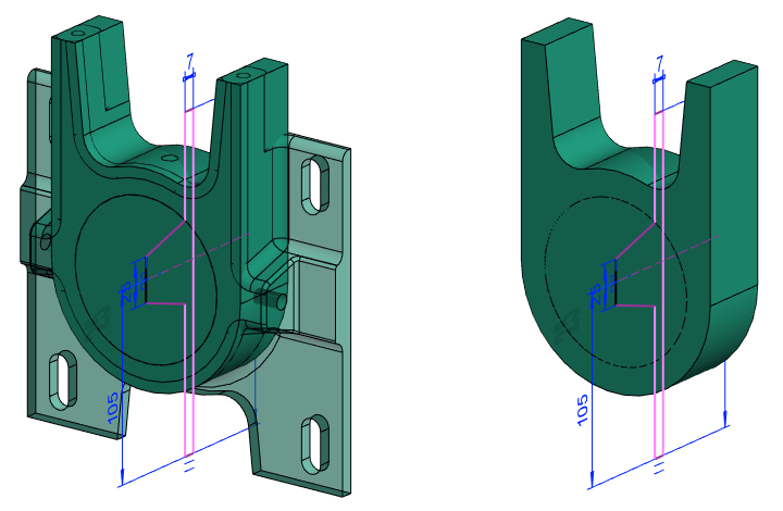
With the sketch option Original Geometry Visible, you can choose whether to display part of the entire history until the end, or to display it only until the previous step.
-
If you select to Original Geometry Visible, the history of the model is drawn to the end or to the history pointer.
-
If you do not select a Original Geometry Visible, then the part will be drawn in the same style as when the sketch was being added (i.e., the "future" will not be displayed).
Until version 27.0.XX, the history of a model was always presented drawn to the end (= drawn to the history pointer), even if you were editing from the sketch of the previous feature.
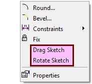
Draft Sketch and Rotate Sketch are removed from right-click menu
After selecting the point, the functions Draft Sketch and Rotate Sketch in the right-click menu of the sketch have been removed as practically unnecessary, while the drag functionality of the sketch has been internally renewed.
-
Instead of Drag Sketch, use Clipboard > Cut and Clipboard > Paste.
-
Moving geometry with the clipboard, allows geometry selection, unlike that old deleted feature.
-
Note that the Ctrl A selects all geometry from the sketch.
-
-
Instead of Rotate Sketch, use Clipboard > Cut and Clipboard > Paste.
-
When Paste, use the Rotate Left and Rotate Right functions.
-
Part
Drag the feature into place
Until version 27.0.XX, the location of a library feature could not be changed by dragging, but only by adding constraints. In some cases, this resulted in extra work.
You can drag features in sketch mode near the right place before giving them an exact location using the constraints.
-
Dragging is successful within the given constraints even later when you return to edit the sketch of feature.

-
Keep the automatic preview on when you later drag a feature from the draft, then the current location of the feature will not fool you.
Note that the perpendicularity of the feature added to the cylindrical face to the face is not preserved during dragging, but the feature retains its original orientation.
-
If necessary, use the Relocate function for the sketch.
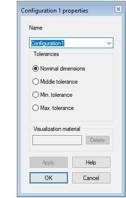
Name the configuration as you create it
When you create a new configuration, the program opens the Properties of X feature, so you can immediately rename the configuration.
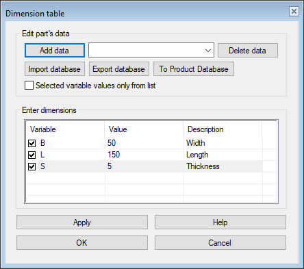
Enter descriptions for the variables in the dimension table
You can now provide a description of the variables related to part model (Variables which you can enter in sketch, actions, and other features). The description facilitates the identification of variables.
-
Right-click function: Dimension Table opens a dialog where you can enter descriptions of the variables.
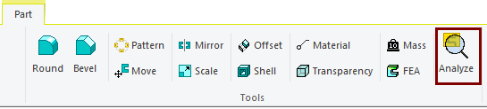
Analyze the part model
Sometimes the behavior of a part model may be surprising and you need to figure out why it is behaving differently than usual.
Now the model analysis tools have been gathered in one place from which the analyzes can be easily performed.
If you approach Vertex Systems Oy's support service for any problems with your models, we recommend that you always attach the model to your support request first. If for some reason this is not possible, perform a full analysis of the model (with the Select All option) and copy the entire text to the problem report.
Analyze the part model with the Analyze toolbar function. This function opens a dialog where you can select the objects to be analyzed. Use the Apply button to perform the analysis and list the findings in a dialog.
-
Note that you can copy text from the dialog using the clipboard.
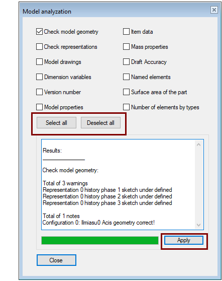
Items to be analyzed
Check model geometry
-
The program analyzes the sketch constraints and reports under- or over-definitions of the sketches.
-
Note that Vertex G4 does not force you to make sketch that are fully defined with constraints. In particular, sketch of dimensionally variable models (such as those used in Product Automation System) should be fully defined.
-
The program also analyzes the flawlessness of the Acis geometry of the configurations in the model.
Check configurations
-
The analysis prints the number of configurations and the names of the configurations in the model.
Model drawings
-
The analysis prints the number of drawings in the model and the names of the drawings.
Dimension variables
-
The analysis prints the variables in the model, including the variables in the model features.
-
You can also see the variables in the model by moving the cursor to the main symbol in the feature tree.
Version number
-
The analysis tells you which version of the model was originally made.
-
Note: If the model was made with a version older than 15.0.00 (released in September 2008), then the program will not find such information about the model, so it will give a blank answer.
Model properties
-
The analysis indicates whether the part is shown in the assembly parts list or assembly drawing, how the part symmetry is defined (this is important if the part is mirrored in the assembly), whether the part auxiliary geometry (construction lines and planes) is shown in the drawing and and whether the part is permitted to be machined with a machining feature or, if the part is transparent, whether it is shown in the assembly drawing.
-
The Right-click function: Properties opens an dialog where you can change properties.
Item data
-
The analysis tells you the model item ID and description or the item is missing.
Mass properties
-
Analyze part volume, mass and center of gravity location, and moments of inertia with respect to center of gravity.
-
You can get the same information with the Mass function.
-
You can influence the density that significantly affects the mass with the right-click function Item Data, where the material iten or material used is stated.
Draft Accuracy
-
Analyze the drawing resolution used by the program (Tolerance or Angle tolerance and report the number of face triangles). The analysis also tells you if the default tolerances for the Acis modeler are in use, or some other values.
-
Note that the number of face triangles is multiplied only if the Draft Accuracy has been changed first.
-
You can adjust the draft accuracy using the Draft Accuracy function in the View ribbon in the Settings group.
Named elements
-
The analysis tells you the named elements used in the model, if any have been added to the model.
-
The most commonly named element is the handle that controls the placement of the components. After selecting a point, you can add a handle with the Right-click function Add Handle.
-
You can add, delete, and edit named elements with the right-click function Other Functions > Edit Named Elements.
Surface asea of the part
-
Analyze the area of a part. This is therefore the "painting area" of the part and not, for example, the area of the sheet metal required for the sheet metal part.
Number of elements by types
-
The analysis tells the types and numbers of the geometric elements.
-
This information tells to how much of your computer's resources are needed.
-
The information can be useful when wondering about the strange behavior of imported parts; Planar surfaces are spline surfaces, in which case it is not possible to assign distance constraint to them.
-
You can change the planar spline faces of the imported parts to plane faces with the right-click function ACIS Geometry > Healing and then with the Simplification Settings