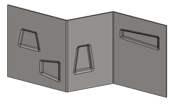
Exercise 9: Shaping sheet metal feature
This exercise was carried out with version 27.0 (Vertex 2021).
In this exercise you will learn to
-
The way to create a sheet metal feature that shapes the part. Technically, the feature first removes the piece of part and then adds new geometry instead it.
-
Write expressions in the formula field in the sketch and in the operates.
-
Adding a handle to the model. The handle is later used to position the feature in the part model.
Functions to be used:
-
Sketching: Adding a line, line properties, copying a line to a sketch, coincident, symmetry, and distance constraint.
-
Operation: Boss and Extrude, also with Make Tool
-
Add Round/Bevel > Round and Add Round/Bevel > Single Edge Round
-
Shell
-
Properties (of part)
-
Handle
-
Save To Library > As Feature
-
Model the shape of the feature as dimensionally variable, where the material thickness of the plate is expressed by the variable: t.
-
As a final step, model a tool that removes the required piece from the sheet.
-
Add a handle to the model. The feature is placed using the handle.
-
Change part properties to: Sheet Metal.
-
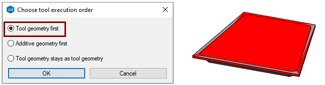
Save as a feature to the library (Tool geometry first).
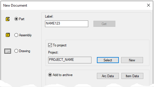
Create a new part
-
File > New > Part.
-
Enter the label (which is also the name of the model and by default will be the name of the drawing).
-
Enter the archive information by clicking Arc.Data.
-
Select the project where the model will be saved.
-
OK.
-
Create the first feature
-
New Sketch > To horizontal (XY) vertical (XZ) lateral (YZ) plane.
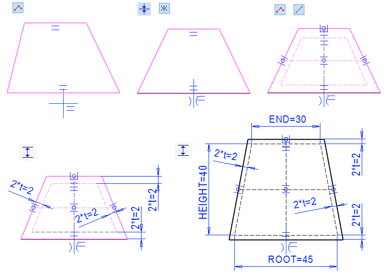
Sketch the shape
-
The function: Polyline.
-
The Shape line has a sketch main shape, on the basis of which a Tool is also made.
-
The Guide line around the edges has an outlined shape from which the edge of the cup begins. It is dimensioned 2 * t (i.e. 2 * material thickness) from the edge of the main shape. This is because rounding by material thickness (t) can fit in the model.
-
-
The function: Two Point Line.
-
Sketch two more guide lines (* 1)
-
For example, a vertical guide between the center point of the horizontal lines. Sketch a horizontal guide line in two sections so that it starts from the center of the oblique line horizontally and ends at the vertical line. And another line from it horizontally to another oblique line.
-
-
Add dimensions to the guide lines:
-
Value: 45, formula: ROOT
-
Value: 30, formula: END
-
Value: 40, formula: HEIGHT
-
value: 2, formula: 2*t
-
-

Operation
-
Boss - Extrude.
-
Change the extrusion direction downwards (so that the horizontal and vertical guide curve lines remain on the top of part).
-
Lenght: 1 formula t.
-
The handle needs a point and the handle should be located on the top surface of the feature.
You can also model the guide lines required for the handle later on the model surface, so that the extrusion direction mentioned above does not need to be changed.
The significance of the guide lines is that a handle is later added to the model to guide the placement of the feature.
-
A point is required for the handle.
-
Guide lines can also be used to aid in feature placement.
Model the rough shape of the cup
-
Click the underside of the part (turn the part if necessary).
-
Right-click function: New Sketch > Face.
Sketch the shape
-
The function: Copy lines (Or right-click function: Line > Copy to Sketch Plane)
-
Click to the four guide lines around the edges and confirm with OK or

-
If necessary, change the lines to a Shape line (They are the type of line you last used to sketch the lines).
-
-
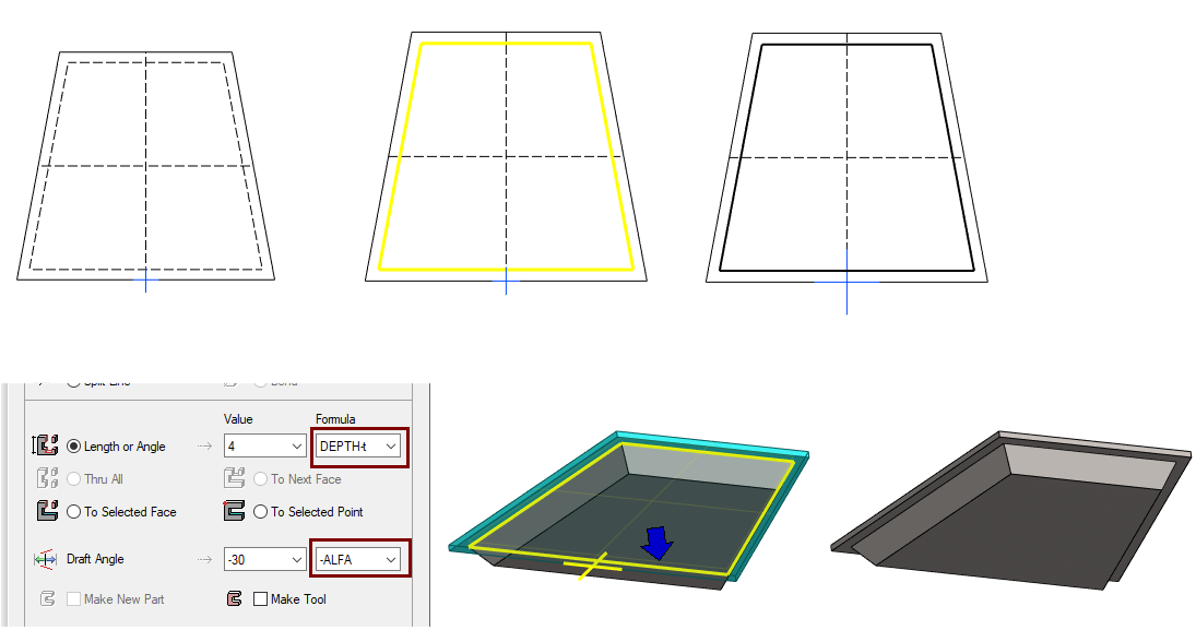
Operation
-
Boss - Extrude.
-
Lenght: 4, formula: DEPTH-t.
-
Draft Angle: -30, formula: -ALFA.
-
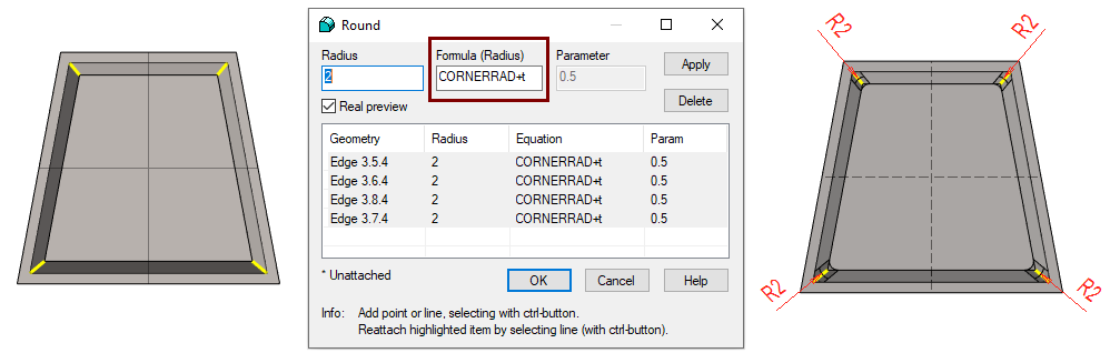
Add roundings to the corners of the cup
-
Click four corner lines (Remember

-
Right-click function: Add Round/Bevel > Single Edge Round
-
Radius: 2
-
Formula: CORNERRAD+t
-
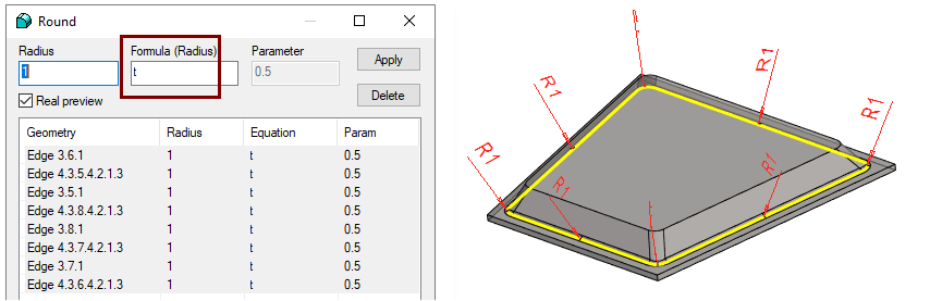
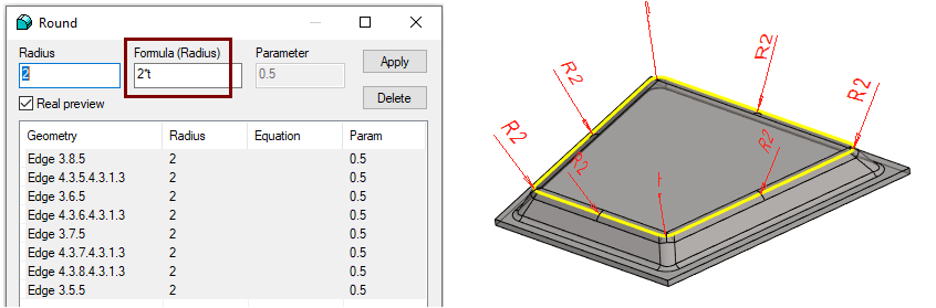
Add rounding chains
-
Click a single line (in the lower figure).
-
Right-click function: Add Round/Bevel > Round
-
Radius: 2
-
Formula: 2*t
-
-
OK.
In this exercise, it is assumed that the roundings inside the stamped cup are equal to the thickness of the sheet metal.
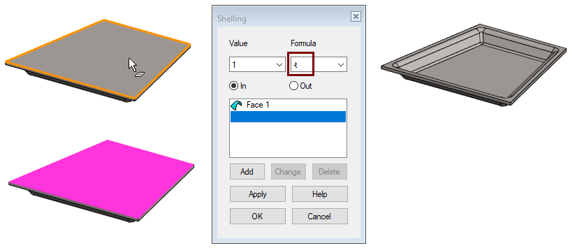
Finish the shape of the cup
-
Click to the top face of the part.
-
Right-click function: Shell
-
Select: In
-
Value: 1.
-
Formula: -t. (Note the minus sign that indicates that the Shell is made inward).
-
-
OK.
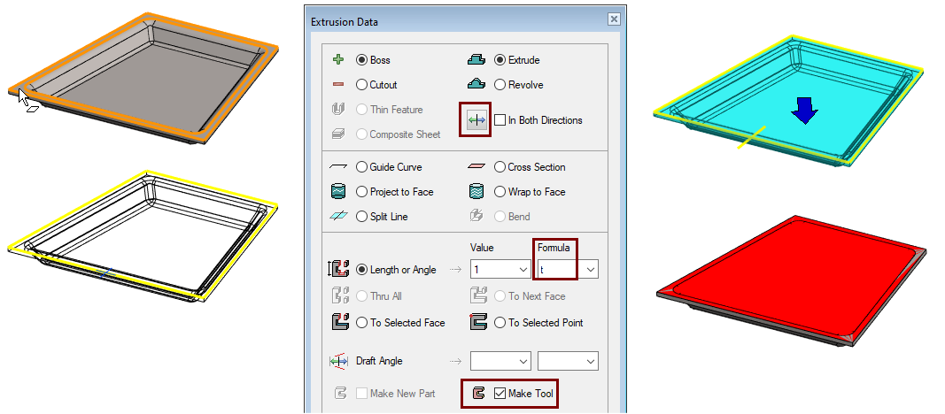
Model the machining feature
-
Click to the top face of the part.
-
Right-click function: New Sketch > Face.
Sketch the shape
-
The function: Copy lines (Or right-click function: Line > Copy to Sketch Plane)
-
Click to the four edge lines and confirm with OK or
Operation
-
Boss - Extrude.
-
Change the extrusion direction downwards.
-
Lenght: 1
-
Formula: t.
-
Select: Make Tool.
-
-
OK.
Save the model
If a some feature has gone wrong and there is problems with variation, then there is a saved model as a backdoor that has not yet been varied.
-
File > Save or click


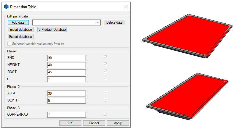
Test the variation of the model
-
Right-click function: Dimension Table.
-
Enter different (reasonable) values.
-
Be sure to also try the value t that varies the thickness of the plate.
-
If t = 2, the value of DEPTH must be at least 5, otherwise the variation will not succeed.
-
If t = 3, the value of DEPTH must be at least 7.5, otherwise the variation will not succeed.
-
Change the model type to sheet metal
-
Right-click function: Properties
-
Change type: Normal > Sheet Metal.
If you forget to change the type to sheet metal, then the feature cannot vary according to the thickness of the sheet metal.
-
The programmatic variable for sheet metal thickness is t (lowercase letter t).
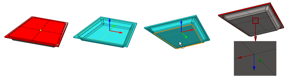
Add a handle
-
Click the endpoint of the line from the top of the feature.
-
Right-click function: Add Handle.
-
The program adds a handle (coordinate symbol) and asks "Location point connection: Show z-direction plane or 1st direction point (x,a)".
-
-
Turn the part and point to the bottom face of the part.
Save the feature to the library
-
Right-click function: Save to Library > As feature.
-
Select (default selection): Tool geometry first.
-
Select the features folder or its subfolder as the storage location. If necessary, create a new subfolder for this type of feature.
-
Enter a name for the feature.
-
Answer: No, when the program asks "Use feature to be Flattened".
Save the model
Although the feature is stored in the library, you should also save the model in the archive if, for example, you want to edit a different feature later.
-
File > Save or click
Test the library feature
-
Create a new part model.
-
Create a piece of sheet metal.
-
For example, sketch a line chain.
-
Extrude into the Thin Feature, eg 1.5mm thick.
-
-
Open a browser

-
Right-click function: Refresh Browser.
-
Find the feature in the folder where you saved it.
-
Click the feature (only once).
-
Right-click function: Library feature > Boss (or cutout, it doesn't matter now).
-
If necessary, vary the dimensions of the feature.
-
Place the cursor and feature on the desired face and, if necessary, turn it using the help menu before clicking to the face.
-
Use constraints to locate the feature.