

Exercise 8: Oblique Duct
This exercise was carried out with version 27.0 (Vertex 2021).
In this exercise you will learn to
-
How to use a jig to model sheet metal parts.
-
How to copy a face from another part.
-
How to create a sheet metal part from a surface chain.
-
How parts are positioned using coincidence constraints.
Functions to be used:
-
New > Part
-
Faces > Copy Face > To volume.
-
Add Flange.
-
Operation:
-
In the assembly: Clipboard> Copy / Paste.
-
In the assembly: Coincidence constraint between surfaces and Coincidence constraint between lines.
-
Create a new part in the assembly.
-
Copy the surface chain of the Jigi part into a volume model.
-
Add flanges.
-
Copy parts.
-
Use constraints to locate the parts.
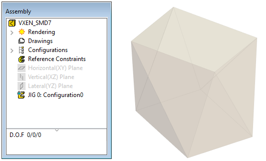
Starting point
In the past, an assembly has been created in which the jig has been modeled.
-
Continue doing this exercise in the previous exercise model.
-
If you have not yet modeled a jig, see the instructions from the previous exercise.
-
You can also download a model from the end of the previous exercise.
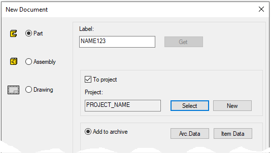
Create a new part in the assembly
-
Right-click function: New > Part.
-
Enter the label (which is also the name of the model and by default will be the name of the drawing).
-
Enter the archive information by clicking Arc.Data.
-
Accept (or create a new) project, where the model will be saved.
-
OK.
-
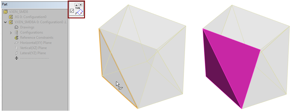
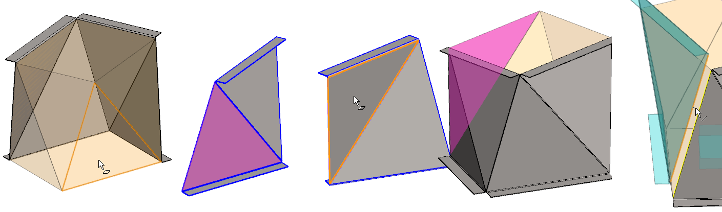
Copy the surface of the jig into a sheet metal part.
-
Right-click function: Faces > Copy Face.
-
Select TAN in the upper left corner of the desktop, ie the selection of the tangential surface chain.
-
Click a face.
-
The program searches for tangential surfaces.
-
-

-
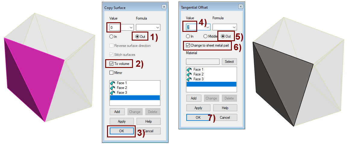
Dialog Copy Surface opens.
-
-
Leave the value: 0 (the surface is copied exactly to the location of the old surface), shown in the figure.
-
Click: Out, shown in the figure 1).
-
Select: To Volume, shown in the figure 2).
-
OK, shown in the figure 3).
-
Dialog Tangential Offset opens.
-
-
Enter the sheet metal thickness value: 2, shown in the figure 4).
-
Click: Out, shown in the figure 5).
-
The sheet metal comes out of the surface.
-
-
Select: Change to sheet metal part, shown in the figure 6).
-
This changes the properties of the part to sheet metal.
-
-
OK, shown in the figure 7).
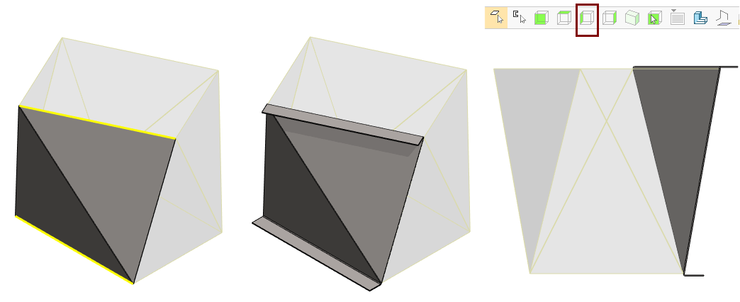
Add flanges (mounting edges) to the part
-
Click to the two lines on the outside edge of the sheet metal.
-
Right-click function: Add Flange.
-
Enter the value:
-
Radius: 2
-
Angle: 90 or 100 (The value 100 found by experiment).
-
Length: 40
-
The program suggests an angle of 90. You can accept it to see if the part looks valid.
-
Turn the projection in the direction: Left View.
-
If necessary, edit the Flange feature (for example, by double-clicking it on the feature tree) and try other values.
Return from part to the assembly:
-
Create another sheet metal part in the same way
-
Right-click function: New > Part.
-
Right-click function: Faces > Copy Face.
-
Right-click function: Add Flange.
-
In this part, the angle 96.4° angle looked good.
-
Return from part to the assembly:
-
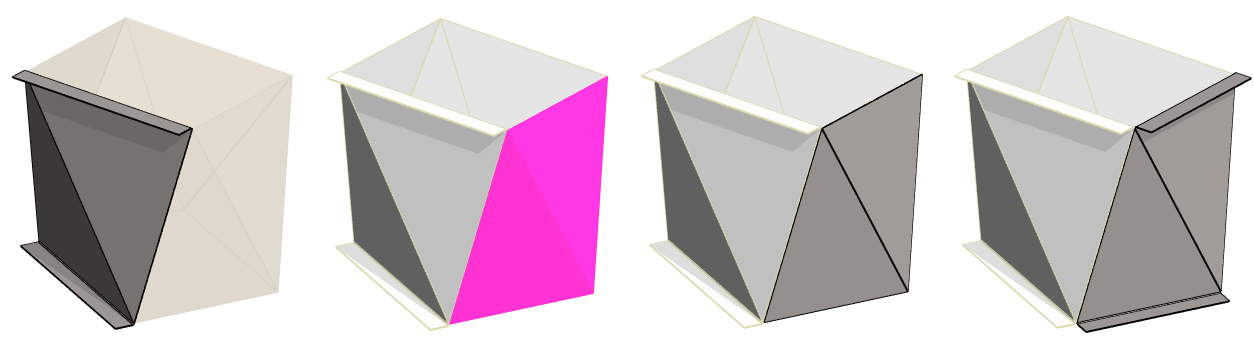
Complete the assembly by copying the parts
-
Click a part.
-
Right-click function: Clipboard > Copy.
-
Right-click function: Clipboard > Paste.
-
Before positioning, turn the part 90 ° twice around the blue axis.
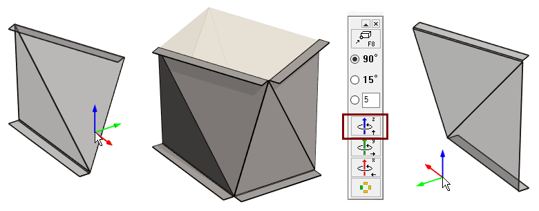
Use the Conincident constraint to locate the parts
Add three Conincident constraint between each part and the jig.
-
Two pairs of faces.
-
One pair of lines.
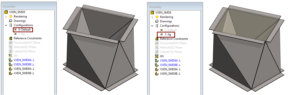
Hide the jig
You should create a new configuration in the assembly where the JIGI part is visible and hide it in the O: Defauld configuration.
-
Click Configurations. (From the feature tree)
-
Right-click function: Add Configurations.
-
Select this new configuration: 1: Configuration 1.
-
Right-click function: Properties.
-
Enter a new name: Eg Jig.
-
OK.
-
-
Activate the configuration: 0: Default (Either double-click or Right-click function).
-
Click the JIG part.
-
Right-click function: Hiding > Hide.
-
Click the configuration: 1: Jig.
-
Right-click function: Update Hiding State.
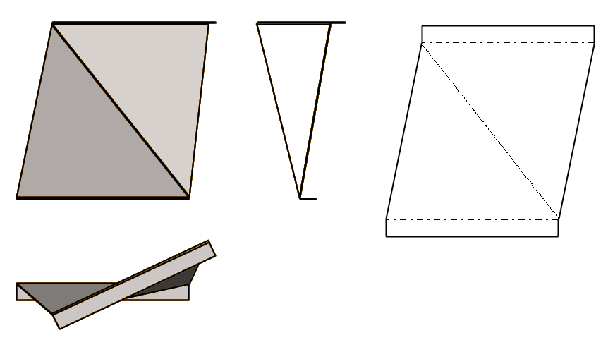
Create drawings for parts
-
Take each part in turn for editing.
-
Enter or select a raw material for the parts (See exercise 2: Box)
-
Create a drawing.
-
Click the Drawings in the feature tree.
-
Right-click function: New Drawing.
-
Select scale (1: 5 to fit geometry on A3 form).
-
Select projections: Front, top, left and Flatten sheet.
-
Save the dawing
-
File > Save or click


-
Remove the drawing from the desktop.
-
Return from part to the assembly
-
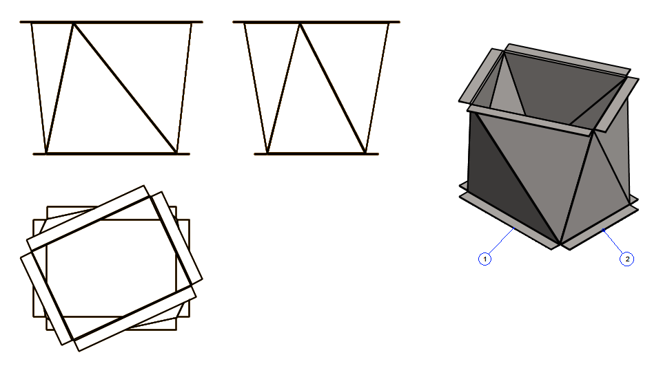
Create a drawing for the assembly model
-
Click the Drawings in the feature tree.
-
Right-click function: New Drawing.
-
Select projections, such as front, top, left, and ISO, -45 front right.
-
Select scale (1:5 to fit geometry on A3 sheet).
-
Add part numbers: Drawing> Machanical > Parts list> Part number.
-
Number > Number
-
Exit the dialog.
-
OK.
-
Click the part (1 and 2) and the location of the part number ball.
-
Save the dawing
-
File > Save or click
-
Remove the drawing from the desktop.
Save the model
-
File > Save or click
Download the assembly model (VX_SMD9.vxz) here.
-
Includes Jig and both different sheet metal parts VX_SMD10 and VX_SMD11.