Exercise 7: Toolbar functions in different modes
This exercise was carried out with version 28.0 (Vertex 2022).
In this exercise you will learn to
-
Use toolbar functions in different modes (Modeling, sketching, and drawing)
-
Check the dimensions.
-
To look at the model from different directions.
-
Record your own views (viewing directions).
-
Limit the visibility of the model.
-
To use local coordinate systems.
-
Viewpoint setting.
-
To fly in the model.
-
Release the model/drawing window outside the Vertex desktop.
-
To use a drawing element selection filter.
-
To zoom in on the drawing.
-
Processing layers of drawing.
-
To rotate the model space either step by step or to make the model rotate continuously.
Functions to be used:
-
Functions of Tool strips
-
Corresponding function in to view ribbon (not all of which are in the toolbar).
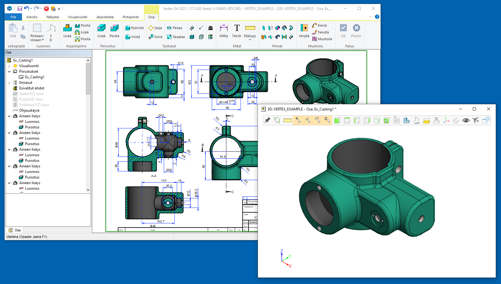
Part and assembly modeling
Open the part model
-
File > Open or press B to open the browser.
-
Browse the models in the archive.
-
Double-click the part model, for example, 1000.
Manage the Tool strip

-
The hidden Tool strip appears when the cursor is over it.

Note: If the working window is narrower than the (horizontal) tool strip or lower than the (vertical) tool strip, the tool strip is hidden, but appears when you move the cursor to its area.
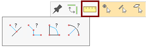
Verify distance

-
Verify distance.
-
Verify path lenght.
-
Verify angle.
-
Verify radius/diameter.

-
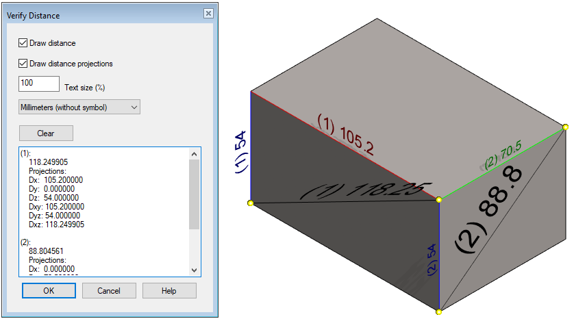
The dialog Verify distance opens.
-
Select Draw distance to draw the shortest line between the indicated elements (point, line, or surface) and add a dimension to it.
-
Select Draw distance projections to draw lines along the major axes between the indicated elements (point, line, or surface) and add dimensions to them.
-
The Text Size field allows you to adjust the size of the dimensions.
-
You can select a unit of dimension. The default is Millimeter (without ID).
-
Use the Clear button to clear the dimension results.
Click two elements (point, line, or surface).
-
The program marks the elements in the model and draws the requested lines and dimensions.
-
The program adds the shortest distance of the elements to the list, also in the direction of the main axes (Dx, Dy and Dz) and also calculates the distances if the assigned points were projected on the base planes XY, YZ and XZ. (Dxy, Dyz and Dxz).

-
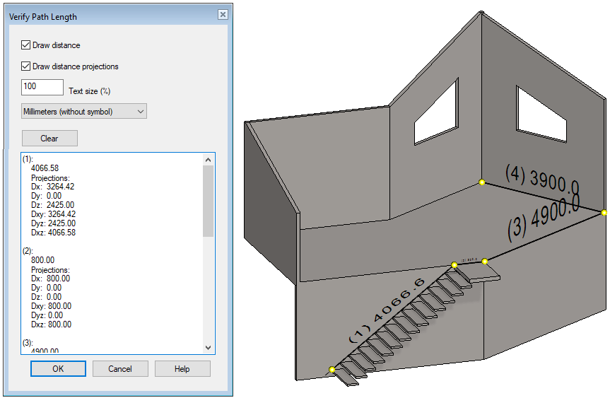
The dialog Verify Path Length opens.
-
Click the path points.
-
The program adds the distances between the points to the list, as above and finally tells you the distance between the first and last clicked point and the total length of the path.
Note that although you can also click to lines or surfaces, the program only uses the points that are assigned to them. For the sake of clarity, only points found in the geometry should be clicked.
-
If necessary, you can also point to points in space or point clouds.
The program numbers the measured distances with a number in parentheses that appears in both the list and the model.

-
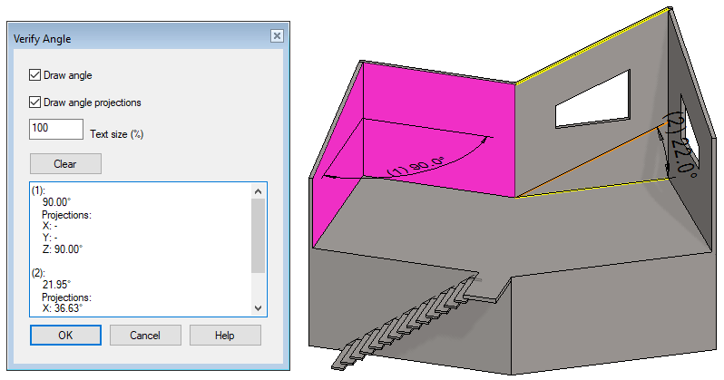
The dialog Verify Angle opens.
-
Select Draw Angle to draw an angle dimension on the model.
-
Select Draw angle projections to draw the angle dimensions along the main projections in the model.
-
Click to lines and surfaces. You can also click points, in which case the program interprets successively assigned pairs of points as lines and tells angles with respect to them.
For lines that are not in the same plane, the program draws a guide to facilitate interpretation in the results.
The program numbers the measured angles with a number in parentheses that appears in both the list and the model.
Angle verifier also accepts circles and elliptical lines, where the angle is calculated from their axis (the normal of the line), and circles and conical surfaces, where the angle is calculated from the surface axis. From the torus surface, the angle is calculated from the surface axis, i.e. the center of the "donut". Spline surfaces or lines are not accepted.

-
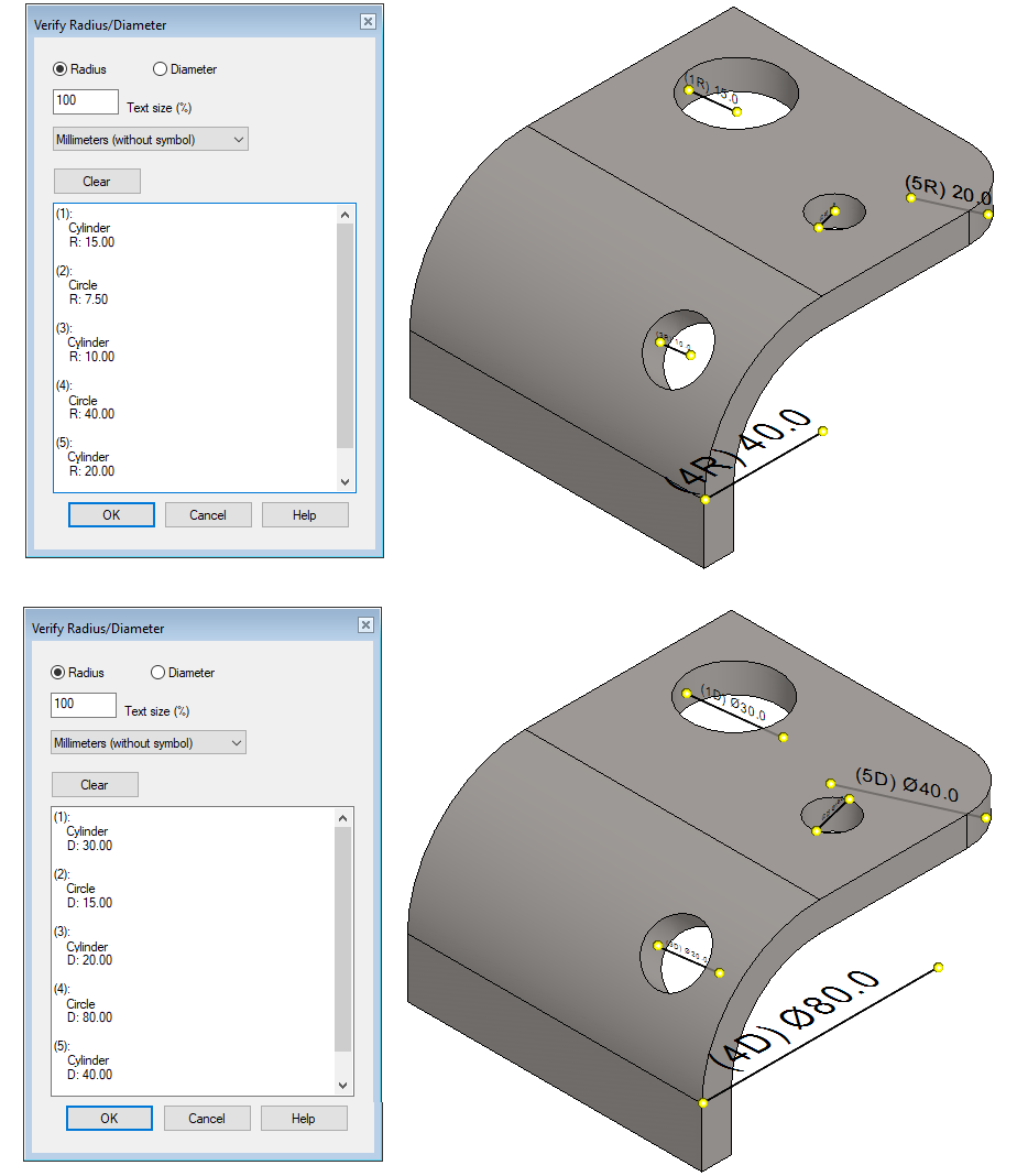
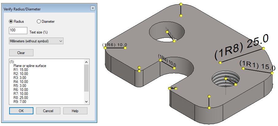
The dialog Verify Radius/Diametr opens.
-
In the dialog, select whether you want the results in radii or diameters.
-
Click to arcs, circles, or cylindrical surfaces.
The program numbers the dimensions that appear in parentheses in the model as well.
-
You can also click to a planar face, in which case the program measures the radii (or diameters of your choice) of the arcs at the edges and center of the surface and lists them.
-
It is also possible to interpret rays from spline faces.
-
The number of the clikced plane is given in parentheses first, followed by the radius/diameter number after the letter R/D.
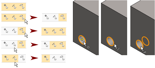
Snap to points, lines, and faces
-
By default, the cursor finds the points, lines, and faces below.
-
Select the elements you want to grab.
Note:
-
If all three are selected and you select one, the other two will be deleted. (second top line).
-
If only one is selected and select it again, then all three will be selected. (third line from the top).
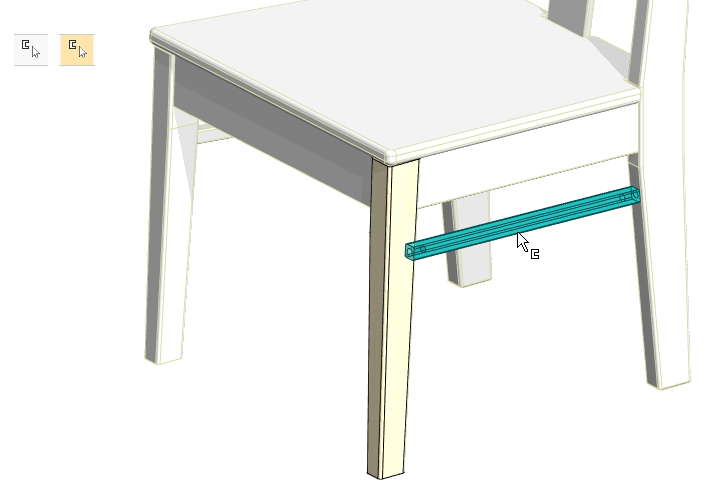
Select other parts when editing a part in the assembly
-
By default, other parts or parts of other subassemblies cannot be selected when you are editing a part or subassembly through the assembly.
-
If Select also other parts when editing a part part or sub-assembly edit mode is selected, you can point to other parts in the working window.
A part can be hidden with the H key, even if no other parts can be selected. All you have to do is press the H key while the cursor is over the part you want to hide.
To hide a sub-assembly structure, hold down the Alt key and click the part to select the configuration instead of the part. The next click selects the top-level subassembly structure, etc., until after selecting the top-level structure, the next click returns to the selection of the part only. In this case, the desired subassembly structure can be hidden with its parts.
You can copy local parts from other subassemblies to the active subassembly via the clipboard.
If Show Geometry Tip in Cursor is selected, you can also view information for parts of the subassembly other than the one being edited.
-
File > User Preferences > Drawings, Models > View tab > Common group > Show Geometry Tip in Cursor.
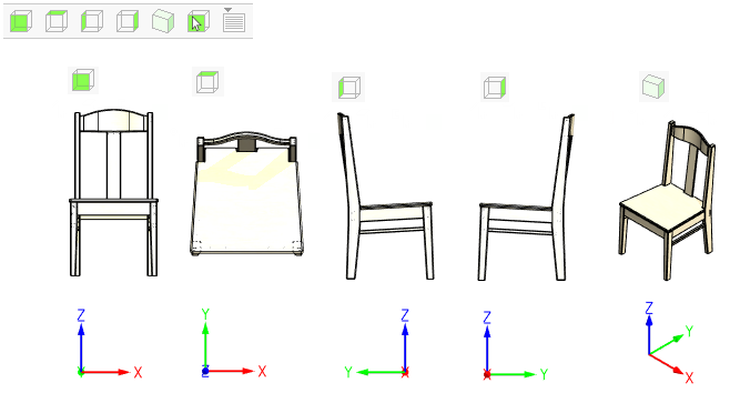
View the model in the desired direction (Projections)
These functions allow you to view the model from different directions. It’s as if you’re “flipping the model,” even if the model doesn’t flip in these cases, you’re just looking at it from different directions.
-
Front view.
-
Top view.
-
Left view.
-
Right view.
-
Isometric view.
-
Select From Model.
-
Other view.
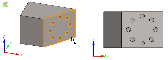
 Select the viewing direction from model
-
Function: Select From Model.
-
Click on the plane face of the model.
-
The program rotates the model so that the face is perpendicular to the image plane.
-
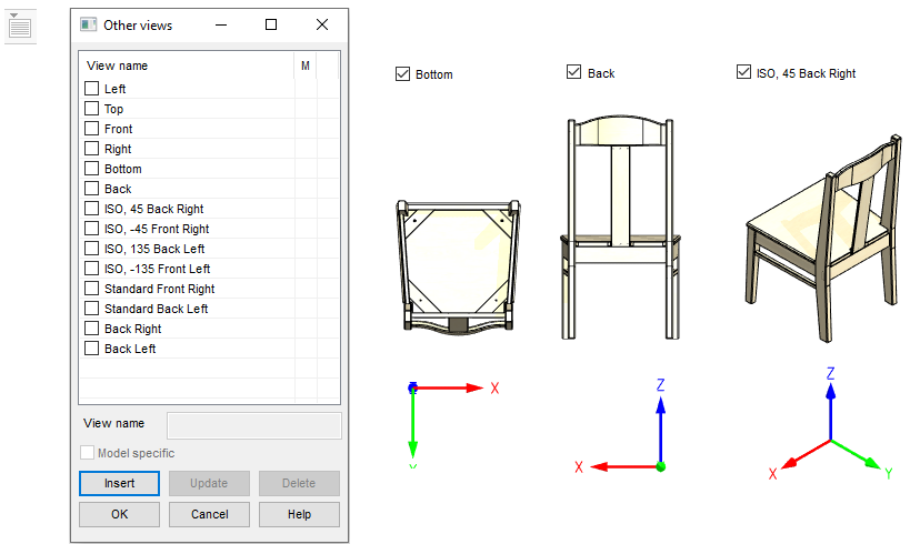
 Select or specify another viewing direction
-
Function: Other view.
-
The dialog Other views opens.
-
-
Select a view from the list.
-
You can change the selection and the model will rotate in the desired direction.
-
-
Press OK to exit the dialog.
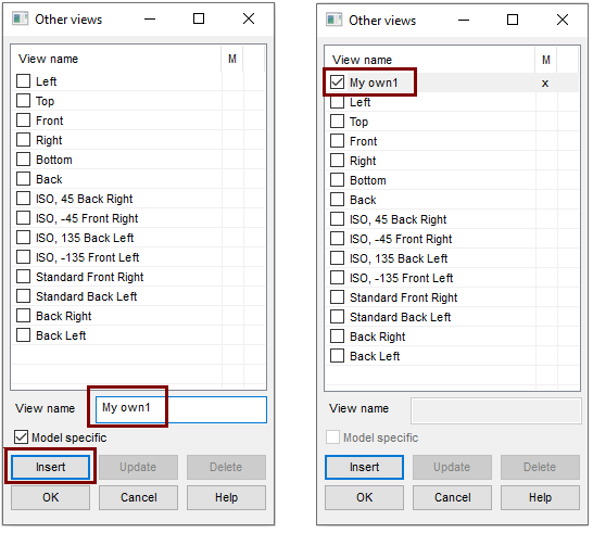
Save your own views (model viewing directions)
-
First, rotate the model in the desired direction.
-
If necessary, choose Perspective from the Projection group on the View ribbon.
-
Function: Other view.
-
The dialog Other views opens.
-
-
Click Insert button.
-
The View Name field is activated.
-
The program adds the Model specific selection.
-
-
Enter a name for the view.
-
If you want to save yourself a general view (available on all your models), deselect Model Specific.
-
OK saves the view.
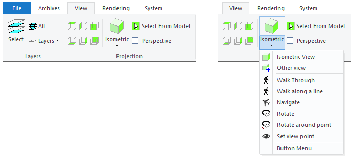
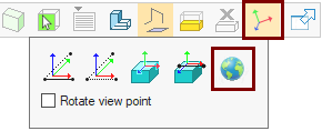
View ribbon projection functions
The View ribbon includes all of the above features, plus:
-
Check box Perspective to turn perspective on and off.
-
Walk Throught.
-
Walk along a line.
-
Navigate (The function is described later in this exercise).
-
Rotate.
-
Rotate around point.
-
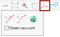
Set view point (The function is described later in this exercise).
View ribbon: Walk Through
The function allows the model to travel at a "constant height".
-
Function Isometric > Walk Through from the Projection group on the View ribbon.
-
The program sets the model to perspective view.
-
-
Calmly move the cursor in the working window:
-
Hold the cursor in the middle: The model stays in place.
-
Move the cursor to the left. The model "rotates" around the vertical axis to the right, the faster the more the cursor is on the left.
-
Move the cursor to the right. The model "rotates" around the vertical axis to the left, the faster the more the cursor is on the left.
-
Move the cursor up. The model comes towards you and you can go through the model.
-
Move the cursor down. The model goes further.
-
The program shows the travel speed m/s and the turning speed degrees/s in the message line.
-
-
Press

If the model is missing, press 
Walk inside the model first before you start "rotating the model," that is, turning your gaze to the right or left.
View ribbon: Walk along a line.
The function allows you to use points to determine the route to be taken and, if necessary, to produce a video of this. The process is presented as an animation.
-
Function Isometric > Walk along a line from the Projection group on the View ribbon.
-
Click on the points in the model to be traversed and acknowledge Done when the points are assigned.
-
Done-acknowledge:


-
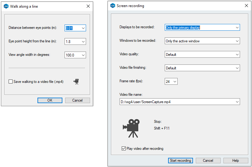
The dialog Walk along a line opens.
-
-
Enter the Distance between the eye points (in meters). The default is 0.01 i.e. 1cm.
-
Enter the Eye point height from the line (in meters). The default is 1.8m.
-
Enter the View angle width in degrees. The default is 100 degrees.
-
If you want the animation to be saved as a video, select Save walking to a video file (.mp4).
If you selected to Save walking to a video file (.mp4), the program opens the Screen recording dialog, which is the general video dialog.
-
Leave the default for recordable Displays and windows. Only the primary display and Only the active window are sensible options in this case.
-
If necessary, you can influence the quality and finish of the video and the frame rate.
-
Enter a name and location for the video file.
View ribbon: Rotate (model space)
This function allows you to make the model space rotate around vertical or horizontal axes in the center of the image plane.
-
Function Isometric > Rotate from the Projection group on the View ribbon.
-
Use the arrow keys to control the direction of rotation.
-
Right arrow = Rotates the model space counterclockwise with respect to the vertical axis. (Or stop clockwise rotation).
-
Left arrow = Rotates the model space clockwise with respect to the vertical axis. (Or stop counterclockwise rotation).
-
Up Arrow = Rotates the model space relative to the horizontal axis so that the top edge of the model hides (or stops rotating in the other direction).
-
Down Arrow = Rotates the model space with respect to the horizontal axis so that the bottom edge of the model hides (or stops rotating in the other direction).
-
-
Use the number keys to set the rotation speed (1 ... 7).
-
1 = slowest.
-
2 = reasonable.
-
3 = fast.
-
4 ... 7 = unnecessarily fast speeds, ie jumps at too high angles.
-
-
Stop rotating the model:
-
-
Middle mouse button or
-
click the working window.
-
View ribbon: Rotate around point.
This feature allows you to rotate the model space around the clicked point one step at a time or by continuous rotation.
-
Function Isometric > Rotate around point from the Projection group on the View ribbon.
-
Click the point that serves as the center of rotation.
-
Use the arrow keys to rotate the model one step.
-
Right arrow = The model rotates one step counterclockwise (around a vertical axis drawn through a point).
-
Left arrow = The model rotates one step clockwise (around a vertical axis drawn through a point).
-
Up Arrow = The model rotates one step away from the top (around a horizontal axis drawn through a point).
-
Down Arrow = The model rotates one step away from the bottom (around a horizontal axis drawn through a point).
-
-
If you press the Shift key at the same time as the arrow keys, then the model rotation is continuous.
-
Use the number keys to set the rotation speed (1 ... 7).
-
The number determines the magnitude of the step in degrees.
-
-
Stop rotating the model with
See the model shaded or wireframe
-
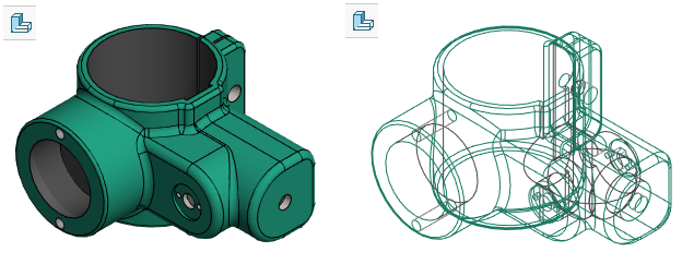
Function Shadet/Wireframe toggles the drawing mode of the model between shaded and wireframe mode.
Show or hide auxiliary geometry
-
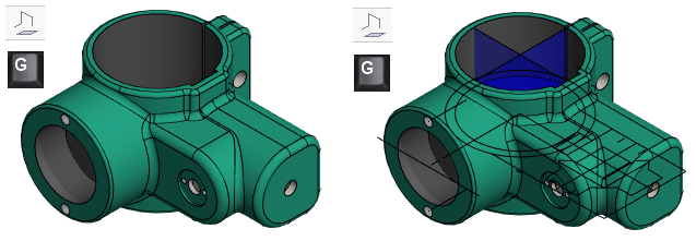
Function Show reference geometry, shows or hides the auxiliary geometry (lines, planes, cross sections, 3d-sketches) shown in the model.
-
The same function can be found with the G key.
-
Auxiliary planes of the part and assembly, as well as features such as control curve and cross section, can be hidden separately.
-
If a plane or a guide curve are hidden, then this function or the G key does not show them.
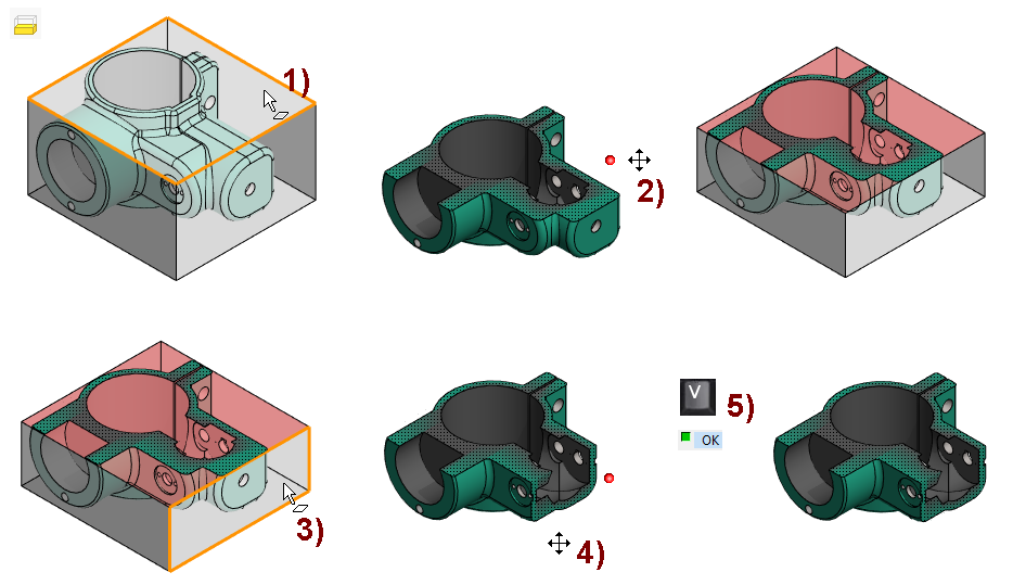
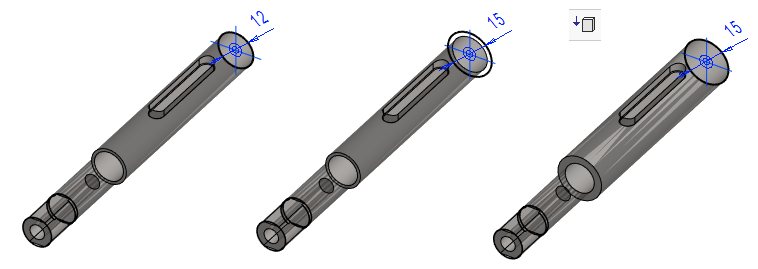
Set 3D limits of model
-
Function: Set 3D Limits.
-
The program draws a cube around the model.
-
-
Select the face of the cube. In the figure 1).
-
Drag it to a new location. In the figure 2).
-
If necessary, select the next face. In the figure 3).
-
Drag it to a new location. In the figure 4).
-
etc.
-
Finish cropping with Done Acknowledgment:
-
With
-
with the middle mouse button or
-
with right-click function
-
Hides the geometry of the "front" part so that "inside" can be seen and operated.
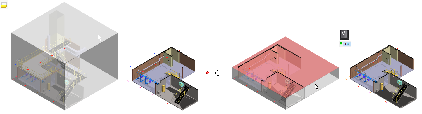
In the assembly:
-
Temporarily simplifies work in the assembly by restricting visible parts.
-
Hides "front" parts or part geometry so that "inside" can be seen and operated.
In the figure on the right , the visibility of the plant model is limited by the upper face of cube.
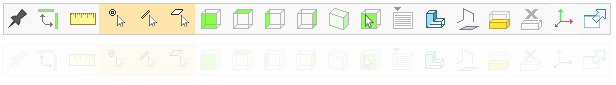
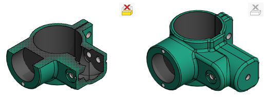
Delete 3D limits
-
Function: Delete 3D Limits.
-
This feature removes the visibility trims made with the Set 3D limits feature at once.
If the model does not have 3D limits, then the the button is gray (see figure on the right).
Set the local coordinate system
Local coordinate systems are mainly used in assemblies and drawings, although the user interface can also be found in the part model.
-
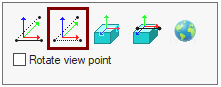
Function: Set Local Coordinate System opens a further menu with functions (starting from the left):
-
Set local coordinate system with a line and point.
-
Set local coordinate system with 3 points.
-
Set local coordinate system on plane.
-
Set local coordinate system on a plane and X-axis according to straight line.
-
Set global coordinate system.
-
When you want to add parts in directions other than the basic coordinate system.
-
When added, the part follows the direction specified by the local coordinate system and the distances are entered according to the directions of the local coordinate system.
When you want to run pipelines in directions other than the basic coordinate system.
-
For the G4, you need either the Mechanical Piping option or
-
G4 Plant-program.
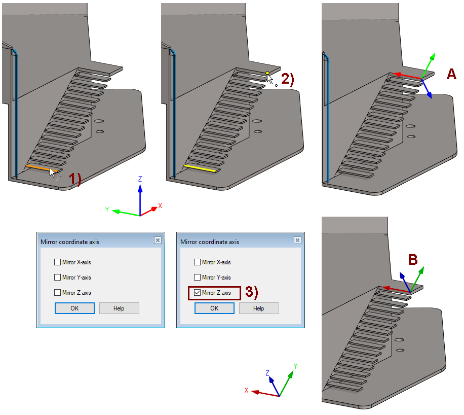
Set local coordinate system with a line and point
-
Click the line that defines the direction of the X axis. In the figure 1).
-
Click the point that defines the XY plane and the direction of the Y axis relative to the line. In the figure 2).
-
The program draws a coordinate axis. In the figure A and
-
the Mirror Coordinate axis dialog opened.
-
-
If necessary, mirror the direction of one of the axes. In the figure 3).
-
The axis is drawn to the new position. In the figure B.
-
The local coordinate system remains in force. The coordinate system at the bottom left of the working window now shows the direction of the local coordinate system instead of the global coordinate system, and the Set Local Coordinate System button on the toolbar is yellow.


After the clicks, the program rotate the model.
-
The function may be more useful on the drawing than on the model.
Set local coordinate system with 3 points
-
Click to the point that acts as the origo.
-
Click the point that defines the direction of the X axis.
-
Click the point that defines the XY plane and the direction of the Y-axis relative to the X-axis.
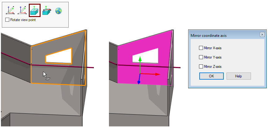
Set local coordinate system on plane
-
Click the plane that defines the XY plane.
-
The program marks the face and searches the edge of the plane for the direction of the X-axis,
-
the Mirror Coordinate axis dialog opened.
-
-
If necessary, mirror the direction of some of the axes.
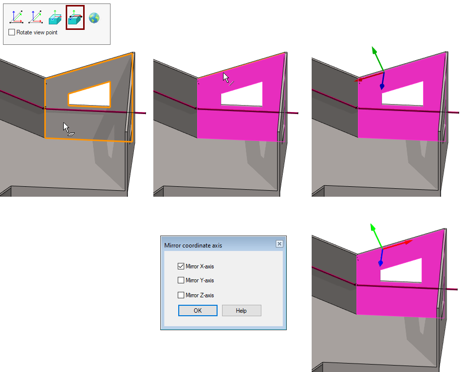
Set local coordinate system on a plane and X-axis according to straight line
-
Click the plane that defines the XY plane.
-
Click the line that defines the direction of the X axis.
-
the Mirror Coordinate axis dialog opened.
-
-
If necessary, mirror the direction of some of the axes.
Set global coordinate system
-
Function: Set Local Coordinate System when the respective button is selected, ie yellow.
-
Function:
Set global coordinate system.
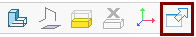
Release the model window from the shackles of the Vertex desktop
-
By default, Vertex's working windows are located on the Vertex desktop.
-
With the Release/Unrelease Window function, you can release the window and move it outside the desktop.
Sketching
Open a part model or create a new part model.
Go to sketch mode
-
For example, New Sketch > Horizontal(XY)Plane or
-
Click a Sketch from the feature tree and the right-click function: Edit.
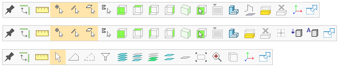
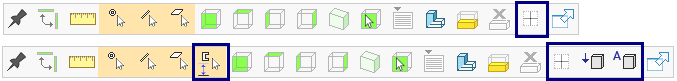
The toolbar in the sketch contains essentially the same functionalities as described above in connection with the modeling toolbar, but functions framed in blue can only be found in the sketch.
-
The toolbar in the top row is available when making a new sketch.
-
The toolbar in the bottom row is available when editing an old sketch.
Use external geometry with sketch constraint
If necessary, you can use the geometry of the other parts in the assembly to add the sketch constraints to other part without copying the parts lines to the sketch (as you still had to in version 27.0.XX).


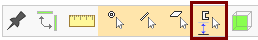
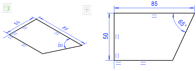
Rotate the sketch perpendicular
-
Function: Perpendicular

-
Rotate the sketch perpendicular to the viewer.
-
When you first rotate the model in another direction or when the Perpendicular setting is not selected.
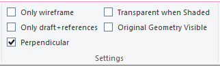
-
If the Perpendicular setting is in effect, then whenever you switch to sketch mode, the sketch is positioned perpendicular view.
-
The same function can also be found in the right-click menu
Use preview when resizing a sketch
To change the dimension of the sketch, you will see a change in the part, when
-
You press the Preview button or
-
immediately if the Automatic preview on/off function is selected.


-
If the button is grayed out, the automatic preview will not take effect.
Drawings
Open a drawing or create a new one
-
The drawing Tool strip has a few of the same functions found on the model (framed in blue).
-
They will not be returned to in the next presentation, except for local coordinate systems, where there are differences from the model.

Select the pointing method

-
Click the element you want to select. To select two or more elements, hold down the Ctrl key at the same time.
-
Rectangle selections: Press and hold the mouse selection button, move the cursor and release the mouse button.
-
Move from left to right: All completely included elements are selected.
-
Move from right to left: All completely and partially included elements are selected.
-


The Done acknowledgment can be implemented with:
-
-
the middle mouse button.

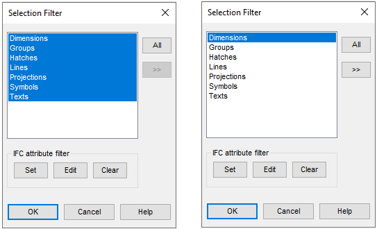
Use a selection filter to assign elements.

If you want to limit the selection to only one type of element (dimensions in the example figure), click this, lines and other selections are turned off.
-
To add or remove element types, hold down the Crtl key while selecting rows:
-
The selected row (blue) is cleared.
-
An unselected line (white) will be included in the selections.
-
-
The All button returns the selection to all types of elements at once.
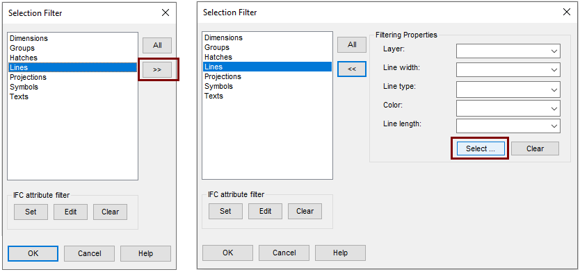
Filter only the elements contained in a specific property
-
Select only one element type first.
-
Then press the >> button.
-
The program opens a menu from which you can select properties.
-
-
If necessary, press the Select button and click the reference element to filter the properties of the assigned elements.
-
You can then use the fence to find those elements that have exactly the same properties as the reference element.
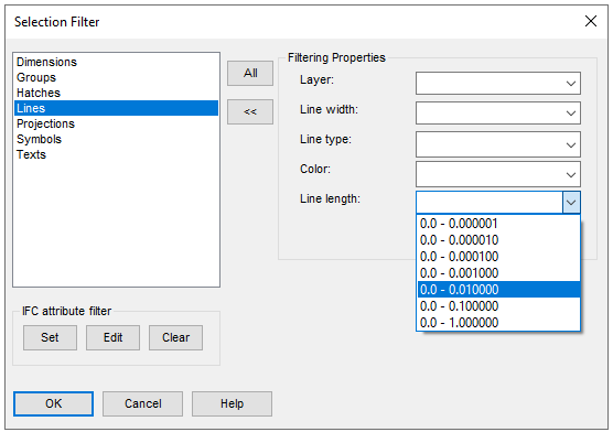
Select short lines and delete them
-
Save the drawing for safety.
-
Function: Selection filter > Lines > expand > select the Line length.
-
OK.
-
Fence the entire drawing area.
-
Press the delete button if the selected lines are unnecessary.
Some imported drawing may have very many non-existent lines that are irrelevant to the drawing but slow to process the drawing (e.g., when the region selection marks the lines selected and later removed). You may want to remove such short lines from the drawing.
Select layers


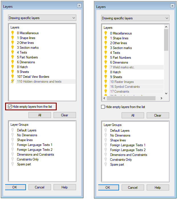
Select Layers from List
-
Function: Select Layers from List.
-
The program introduces all those layers that have elements.
-
-
Click the layer you want to show or hide
Select Layer Groups
Layer groups are listed at the bottom of the dialog. They make it easy to select certain levels to show and hide at once.
You can use the keyword level and level_goups to define names and layer groups for your layers. Note that they are system-specific, meaning that everyone who uses the same Vertex file server will see the same settings.
Edit layers:
Function: File > System Preferences > Edit> Administrator's View > draft> G4 Drafting layers (0..32767) > level(X)
-
Layers 0 ... 255 (ie 256 pcs) have been defined for the system, some of which also have a clear name.
-
Keywords: level (X), where X is the level ID or number, e.g.
-
level(0) {"0 "+MISCELLANEOUS} 1 1
-
level(1) {SHAPELINES} 1 1
-
Edit layer groups:
Function: File > System Preferences > Edit> Administrator's View > draft> G4 Drafting layers (0..32767) > level_group
-
Keywords: level_goups, e.g.
-
level_group {DEFAULTLAYERS} 0 1 2 3 4 5 6 7 8 9 10 11 51 52 107 120 121 122 123 124
-
level_group {SHAPELINES} 0 1
-
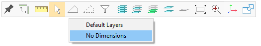
Use favorite level groups
If favorite layer systems are defined, you can select them from the menu opened by Favorite Layer Groups.
-
These are not defined in the delivery version, so the button is inactive
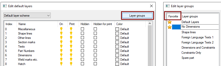
Layer groups can be defined as favorites:
-
File > System Preferences > Default Layers.
-
Click the Layer Groups button.
-
Click the Favorites column (F) for the desired Layer group.
In order for favorite layer groups to appear in your drawing, you must restore the drawing to its default level settings (see below) or create a new drawing.
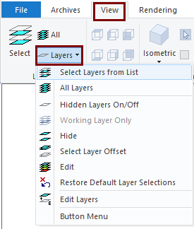
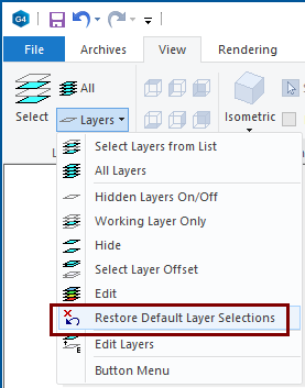
Layers functions in the View ribbon
The View ribbon includes all of the above features, as well as the following features:
-
Edit (layer visibility and properties).
-
Restore Default Layer Selections.
-
Edit Layers.
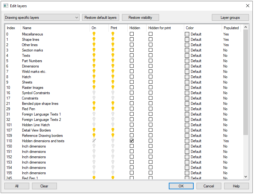
View ribbon: Edit layers
-
Function: View-ribbon > Layers > Edit.
-
The Edit Layers dialog opens.
In this dialog you can e.g.
-
Enter names for layers.
-
However, do not rename already named levels, as levels have established meanings by name.
-
-
Turns the visibility of levels on and off.
-
Turns the printability of layers on and off.
-
When printing, you can choose to print the Visible layers or the Printing Layers defined here.
-
-
Define the level as the hidden level.
-
The hidden level is only displayed when the hidden levels are shown separately with the function: Hidden Layers On/Off.
-
-
Define the layer as the hidden layer when printing, so that elements at that level are not printed.
-
Define the color of the layer.
-
Color of layer is displayed on element in the layer if it have the Color: By Layer.
-
The Restore Defaults layers button restores the system-defined layer definitions for the active drawing.
The Restore visibility button sets most layers to appear both on the screen and for printing.
Replace the layer definitions in the drawing with the layer definitions in the system.
The drawing retains its own layers and groups of layers until the system settings are updated.
-
Function: View-ribbon > Layers > Restore Default Layer Selections.
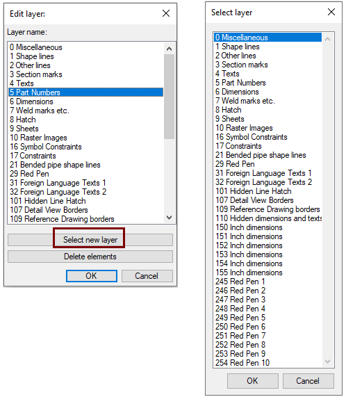
Move all elements in a certain layer to another layer
-
Function: View-ribbon > Layers > Edit Layers.
-
Edit Layer dialog opens.
-
-
In the list, click the layer whose elements you want to move to another layer.
-
The program shows all elements at the layer you selected and hides other elements.
-
-
Click the Select new Layer button.
-
Select Layer dialog opens.
-
-
Click the layer from list to which you want to move the elements.
-
OK, returns to the default layers in the drawing.
Delete all elements at a certain level
-
Function: View-ribbon > Layers > Edit Layers.
-
Edit Layer dialog opens.
-
-
In the list, click the layer whose elements you want to move to another layer.
-
The program shows all elements at the layer you selected and hides other elements.
-
-
Click the Delete elements button.
-
The program confirms the deletion with the question: Delete elements of layer 'X'?
-
-
Answer Yes or No.
-
Note: You can't use Ctrl Z to undo elements deletion, so be careful with this feature and save the drawing before deleting, so you can re-read it if necessary.
Especially imported (DWG and DXF) drawings may have unnecessary elements on the page that you would like to remove.
These can have elements related to the same purpose on several different layers that you would like to see on one layer.
Zoom in the drawing

-
Also hotkeys A and Ä.

-
Also hotkeys Z and Ö.


Other drawing zoom and pan functions
-
Rotate the scroll wheel of mouse.
-
Upwards or away from yourself, bringing the drawing closer.
-
Down, that is, towards you, so that the drawing goes further.
-
-
Note that before zooming, the current cursor position jumps to the center of the working window, so you can also use this to pan the drawing sideways.
Pan drawing
-
Press and hold the middle mouse button as you move the cursor.
-
The drawing moves with the movement of the cursor.
-
Smooth zoom without centering the cursor
-
Hold down the Shift key until you hold down the right mouse button.
-
Press and hold the right mouse button.
-
Move the mouse up and down.
-
As you move the mouse up, the drawing slides closer.
-
As you move the mouse down, the drawing slides farther.
-
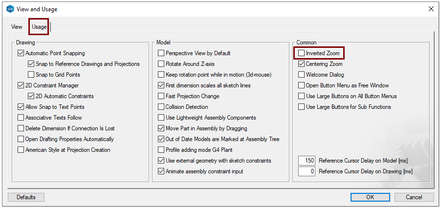
If you think the movement of the mouse wheel is zooming in the wrong direction, then you can change the direction:
Function: File > User Preferences > Drawings, Models> Usage Tab > Common Group > Inverted Zoom.
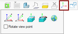
Set the local coordinate system


Option: Rotate view point, rotate the drawing so that the new X-axis is horizontal.