

Exercise 7: Oblique jig
This exercise was carried out with version 27.0 (Vertex 2021).
In this exercise you will learn to
-
How to a new part (local) is created in the assembly.
-
How to create a part from lines and faces.
-
How to give color and transparency for a part to make it easy to use as a jig.
The actual sheet metal parts are modeled in the next exercise.
Functions to be used:
-
Creating a new part in the assembly.
-
New Sketch > Face, Parallel, 3D Skecth
-
Sketching:
-
Operation: Guide Curve
-
Faces > Add Face
-
To volume (Create a part form faces. Add a missing faces.)
-
Add Round/Bevel > Single Edge Round
-
Rendering > Change Material
-
Rendering > Change Transparency.
-
Sketch the inside shape of the jig using the Guide curves.
-
Use these guide curves to add faces.
-
Create a part (volume) of the faces.
-
Add roundings used when creating sheet metal parst with the Tangential offset function.
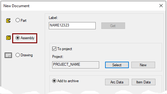
Create a new Assembly
-
File > New > Assembly.
-
Enter the label (which is also the name of the model and by default will be the name of the drawing).
-
Enter the archive information by clicking Arc.Data.
-
Select the project where the model will be saved.
-
OK.
-
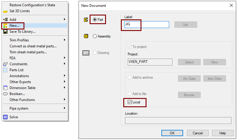
Create a local part
-
Right-click function: New.
-
Click: Part.
-
Enter the label of the part.
-
Select: Local. "Local" means that the part is not made its own file, it is only visible in the assembly.
Create a Guide curve for bottom
-
New Sketch > To horizontal (XY) plane.
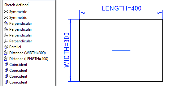
Sketch the shape
-
Sketch a rectangle. The function: Two point rectangle.
-
Click to the first point from the origo.
-
Enter the dimensions: 200,150 and press the enter key.
-
The program draws a rectangle with size 400 * 300.
-
-
If you want the jig to vary in size, edit the dimensions and add a formula to them
Operation
-
Guode Curve.
Create a Guide curve for top
-
Restore the Horizontal (XY) Plane if it is hidden.
-
Click the Plane.
-
Right-click function: Restore.
-
-
Click the To horizontal (XY) plane.
-
Right-click function: New Sketch > To parallel.
-
Enter value 400 and formula HEIGHT
-
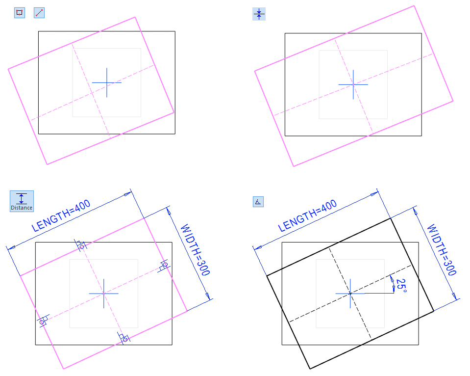
Sketch the shape
-
Skecth a rectangle in an oblique position.
-
Skecth construction lines, between the middle point of lines.
-
Add the Conincident constraints separately for each construction line and ogigo.
-
Add the Distance constrains.
-
400 and formula: LENGTH.
-
300 and formula: HEIGHT.
-
-
Add the Angle constrain
-
25.
-
Operation
-
Guode Curve.
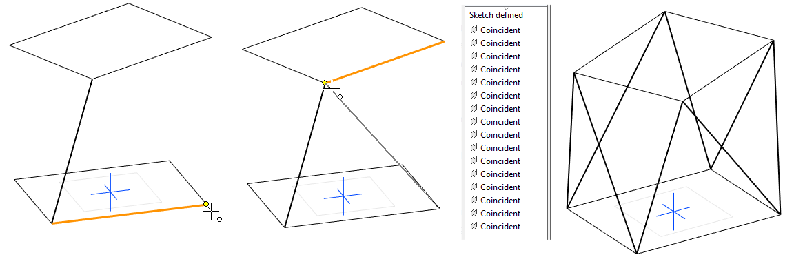
Sketch a 3D guide curve
-
Right-click function: New Sketch > 3D Skecth.
-
Add eight lines as shown in the figure.
-
Make sure the cursor catches the endpoints of the lines and not the lines.
-
-
OK. (Exits sketch mode and makes guide curves).
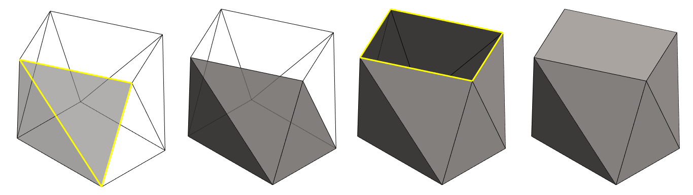
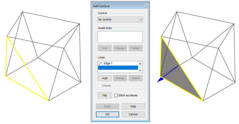
Add surfaces
Surfaces have to be added for each Face (10 pcs) separately.
-
Click three adjacent lines. (Remember the Ctrl key).
-
Right-click function: Faces > Add New.
-
If necessary, change the direction so that the arrow points outwards from the "part".
-
-
Use the option for the following faces: Stitch surfaces.
-
This option to keep the faces to be joined parallel (= outwards from the "part"), so the part (volume) can be easily formed later.
-
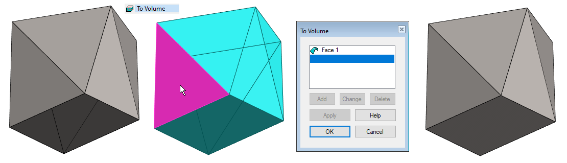
Create a part (volume)
The edges between the surfaces cannot be rounded, so surfaces must first be made a volume.
The surfaces in the model should form a enclosed space, but this is not an absolute requirement. It is allowed for someone or some faces to be missing.
-
Right-click function: To Volume.
-
Click a reference face (Any of these faces are valid).
-
OK.
Note: If you have modeled (all needed) the surfaces so that they delimit the enclosed space from space, the program may not introduce the right-click function: To Volume. In this case, you can create rounds directly to the model.
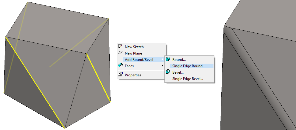
Create roundings
-
Click the four lines shown in the figure. (Remember Ctrl key).
-
Right-click function: Add Round/Bevel > Single Edge Round.
-
Enter the value for the bending radius of the plate, eg: 2.
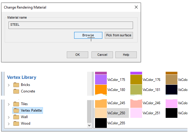
Change the color of the part
-
Right-click function: Rendering > Change Material.
-
Browse materials
-
Vertex Libarary > Vertex Palette >
-
For example, double click the color VxColor_260
-
-
OK.
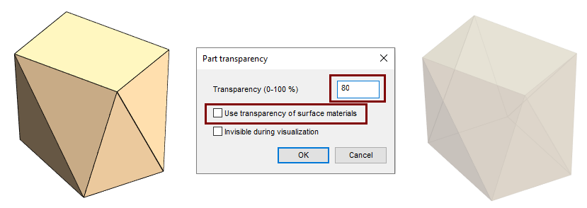
Change the transparency of the part
-
Right-click function: Rendering > Change Transparency.
-
Remove selection: Use tranparency of surface materials.
-
Enter a value for transparency:
-
Eg 80.
-
-
OK.
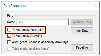
Change the properties of the jig
This part is only used as a modeling aid, so it is not desired to be included in the assembly parts list.
-
Right-click function: Properties.
-
Remove selection: To Assemblu Parts List.
-
OK.
Returns from part modeling to assembly model

Save the model
-
File > Save or click


Video
Duration 2m 31s
For the best quality for your video, watch it:
-
In full screen mode.
-
With a resolution of 1080pHD.