

Exercise 6. How to edit system preferences
This exercise was carried out with version 28.0 (Vertex 2028).
In this exercise you will learn to
-
Principles that allow us to modify settings that affect the Vertex functionality of anyone using the same system (a program installed on the same server).
Functions to be used:
-
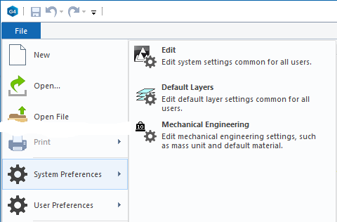
File > System Preferences >
System preferences are divided into three main sections
-
Edit: Setting values.
-
Default Levels: Edit the default levels used in drawings.
-
Mechanical Engineerin: Default values for mechanical Engineerin.
Edit the default Mechanical Engineerin settings
-
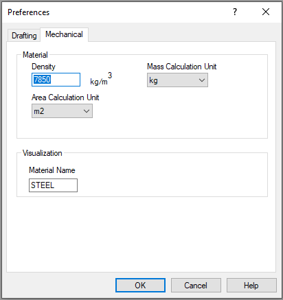
File > System Preferences > Mechanical Engineering.
-
Select the Mechanical tab.
Material section:
-
In the Density field, enter the density of the material you are primarily using. Based on the density and part volume, Vertex calculates the weight of the part model (and the weight of the local parts of the assembly).
-
If a part is given item data or material data that includes density, then the program calculates the weight based on it and overrides the default density here.
-
-
The Mass Calculation Unit tells the unit (tons, kilograms, grams, or milligrams) in which the mass is presented on archive cards and drawings.
-
Default value is kg.
-
-
The Area Calculation Unit tells the unit (m2, dm2, cm2, mm2) where the area is presented on the archive card.
-
Default value is m2.
-
Visualization section:
-
The Material Name tells you what kind of rendering material the models are drawn by default.
-
You can view the names of the materials by: Rendering > Change Material > Browse and then search the library for a suitable material (This does not require the Visualization option for Vertex G4 software, but without it you will not be able to use all the features of the rendering material).
-
The default material is STEEL, but it can no longer be found in the library.
Edit the Drafting settings
-
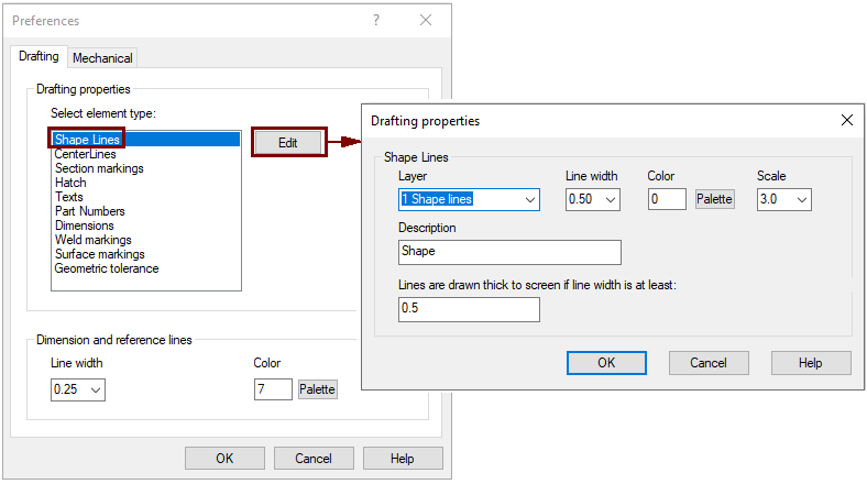
File > System Preferences > Mechanical Engineering.
-
Select the Drafting tab.
-
These settings let you specify drawing options for different types of lines, text, and other elements.
Vertex Systems has tried to adjust the drawing settings in accordance with the standards or traditional drawing methods used in Finland, so modify the values with moderation.
Edit Vertex settings
-
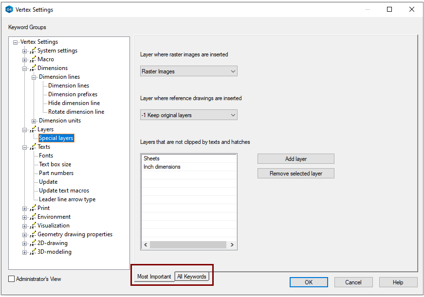
File > System Preferences > Edit.
-
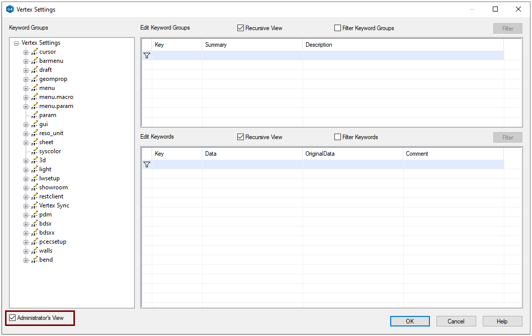
The Vertex Settings dialog open.
-
-
Use the tree on the left to browse key word groups.
-
The All Keyword tab displays all related keywords and their parameters
-
These settings are not meant to be modified for experiment and fun.
In some cases, you may want to change a setting so that Vertex functionality better serves your needs.
-
On the Vertex Settings screen, select the lower left corner function: Administrator's View.
-
Find the keyword whose value you want to change.
-
Change the parameters in the Data field.
-
OK saves your changes.
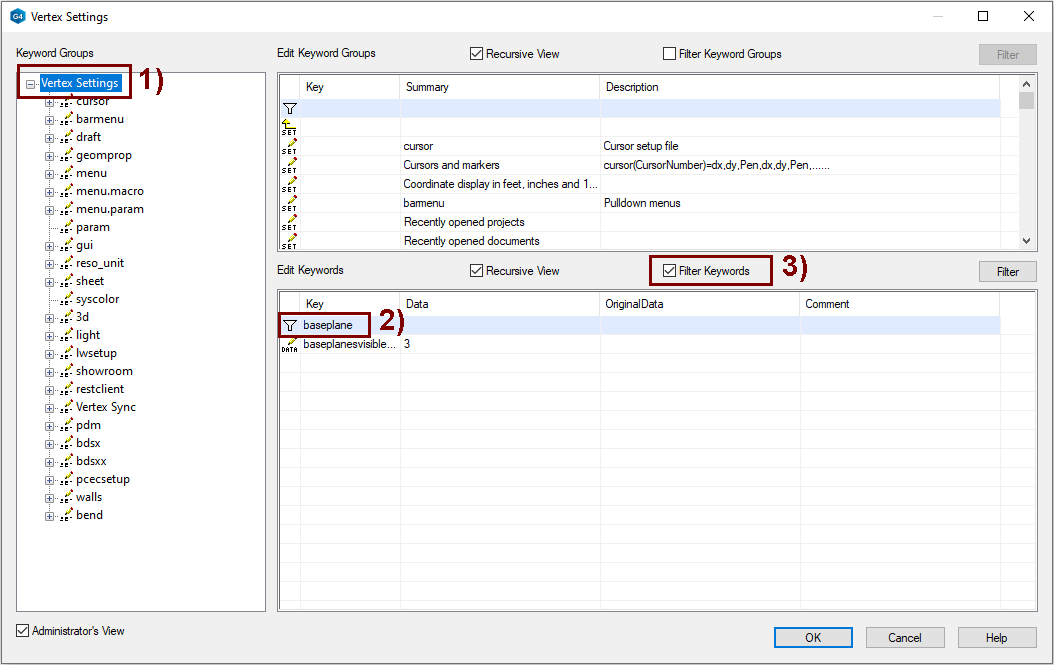
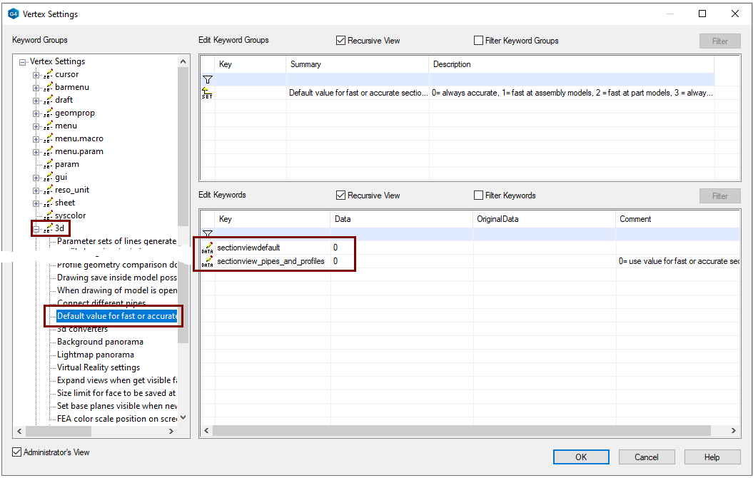
Find the keyword you know
You have been able to get information about the keyword and related parameters through the support service and now you should find that and open it to edit its values.
-
In the tree, select the top item Vertex Settings, in the figure 1).
-
Write the keyword or part of it next to the funnel, in the figure 2).
-
Select Filter Keywords, in the figure 3).
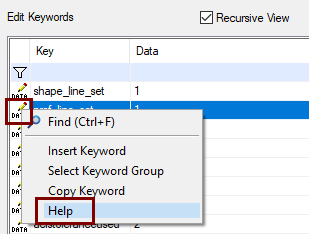
You can access the keyword instructions stored in the system by selecting the Data button in front of the keyword and the right-click function Help.
Edit default leyers
Note that Vertex uses certain predefined layers in multiple functionalities, so do not modify the properties of those layers on a light basis. At the very least, you run the risk that some functionality will not work as intended if you modify the values without more in-depth knowledge.
-
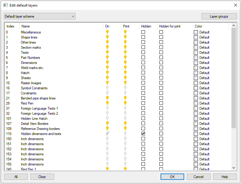
File > System Preferences > Default Layers.
-
The program introduces all designated (Named) levels.
Columns:
-
Index = Layer number, required, must be something between 0 and 32767.
-
Name = The layer should be given a name that describes its intended use.
-
On = On/Off, When a new drawing is made, whether this layer is visible or hidden by default.
-
Print = On/Off, Whether to print the layer if the drawing is printed in the so-called default layers.
-
Today, by default, all currently visible layers are printed.
-
-
Hidden = Elements in a layer are not displayed, even if all layers are shown in the drawing.
-
These layers are only displayed when the function View-ribbon > Layers > Hidden layers on/off is selected.
-
-
Hidden for prints = The hidden layer is also printed.
-
Color = The layer can be given a color that, under certain conditions, appears on the element.
-
When an element is assigned a color: By layer.
-
Saving layer system changes
-
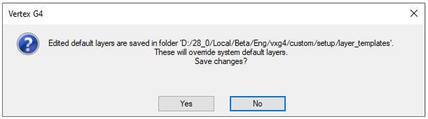
Once you have made changes layers and are leaving with OK, the program will make sure that you want to replace the system default layers with your own leyer.
-
If you answer yes, then the program saves the file in the vxg4\(or vxg4_srv\)custom\setup\layer_templates folder.
-
1 Default layer scheme.vxp, where the layer settings are saved.
-
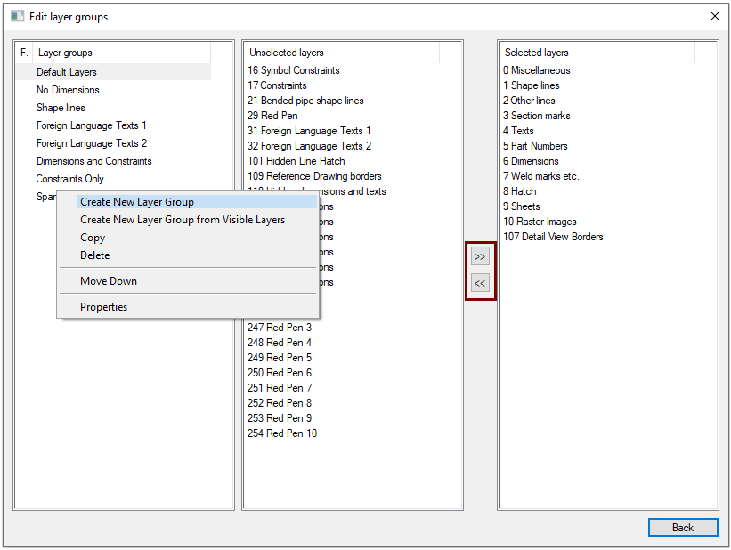
Edit layer groups
Layer groups are used when you want to quickly present some set selected layers in a drawing.
-
Click Layer groups (In the upper right corner of dialog Edit Default Layer).
The left column shows the layer groups.
-
With the help of the right-click menu, you can, for example, create a new layer group.
The middle column lists the levels outside the level group.
The right column lists the levels in the level group.
Move a layer to or from a layer group.
-
Click a layer.
-
Use the arrow buttons between the columns to move the level to another column.
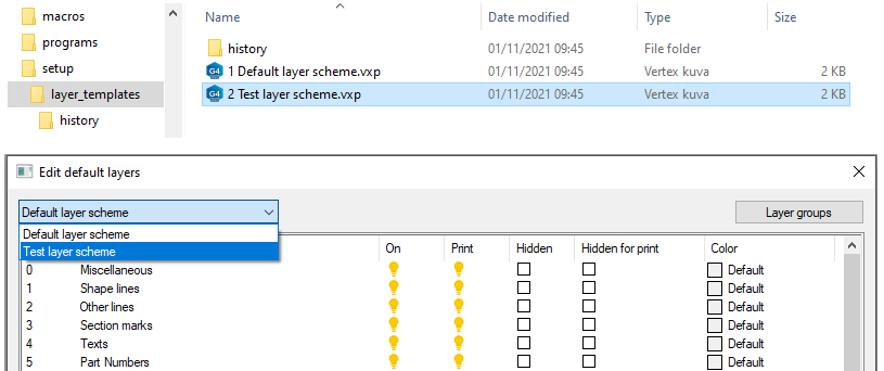
Multiple layer systems
If you edit layer systems, they are stored in the vxg4\(or vxg4_srv\)custom\setup\layer_templates folder as 1 Default layer scheme.vxp
-
Copy it to another name in the same folder and edit the new layer system again.
-
The layer system can now be changed to another layer system if required.
The new drawing inherits the settings of the currently valid layer system.
A couple of examples of keywords
Decide how the section views of the drawing will be implemented by default
By default, the Section projection of the assemblies is of the Quick section type and with the part model of the Accurate cut type. For this reason, the Section projection from the assembly cannot be dimensioned.
-
This is done because it takes a long time to cut and update large models (models with a lot of geometry) because all the parts coming to the cut line have to be temporarily genuinely cut and it takes time.
-
If your assemblies are moderately sized, you could adjust that the cut of the assemblies is also accurate cut by default.
Use the sectionviewdefault keyword to specify the default type of new Section projection.
-
0 = Always a accurate cut.
-
1 = Quick section for assembly models, accurate cut for part models (This is the default, meaning it is valid even if the keyword is missing).
-
2 = Quick section for part models, accurate cut for assembly models
-
3 = Always a Quick section.
You can also change the type of each Section projection individually in the drawing to either accurate or quick.
The keyword sectionview_pipes_and_profiles defines how the pipes and profiles are cut.
-
0 = The keyword sectionviewdefault determines the cutting method. (0 is the default)
-
1 = Pipes and profiles are cut accurate, even if other geometry is cut quickly.
Adjust the visibility of the auxiliary planes
Part and assembly models always have three auxiliary plane symmetrically around the model origo.
-
You can hide and show these auxiliary planes by model and auxiliary plane.
The baseplanesvisiblewhencreated keyword allows you to decide how auxiliary levels appear when you set up a new model.
-
0 = Auxiliary levels are hidden in both the part and assembly models.
-
1 = Auxiliary levels are displayed in the part model.
-
2 = Auxiliary levels appear in the assembly model.
-
3 = Auxiliary levels are visible in both the part and assembly models. (Default setting).
